


30
Mighty Mule 352
1
ON
2 3 4
15
CHARGING
POWER
STATUS
RF
PULL-PUSH
MODE1
MODE2
LOCK/BEACON
OFF 120
MIN MAX
STALL FORCE
CLOSE TIME
SET
LIMIT
LEARN
REMOTE
AUX OUT
SOLAR
PANEL
18VAC
RECR
GRN
BLK
RED
EXIT
SAFETY
EDGE
CYCLE
COMMON
LINK
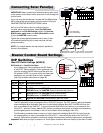
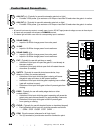
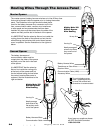
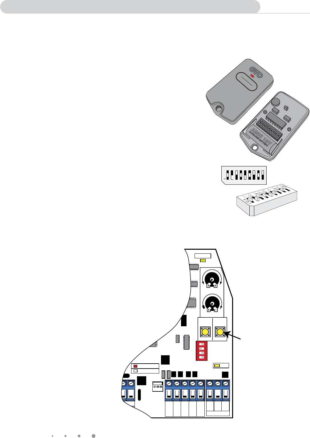
LEARN REMOTE
Button
Master Arm
Control Board
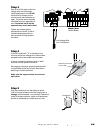
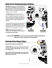
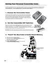
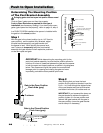
2. Set the transmitter DIP Switches
There are nine (9) transmitter DIP switches; each can be placed in three
different positions (+, 0, –). DO NOT set all the switches in the same
position, such as all +, all 0, or all –. Once the DIP switches have been set to
a personal code, replace and close the access cover.
WARNING: No other adjustments should be made inside the transmitter.
Setting Your Personal Transmitter Code
1. Remove the Transmitter Cover
On the back of the transmitter use a small phillips head screw driver
to remove the two screws on the sides of the visor clip and separate
the front cover from the transmitter. With the front cover removed,
the battery and the DIP switches will be exposed. To set a new code,
use a small screwdriver to move the switches.
All GTO transmitters are set to a standard code at the factory and are ready to operate your Mighty Mule®
352 Gate Opener
®
. For your safety and security, however, we strongly recommend that you replace the
factory setting with your own personal code. Follow the directions below:
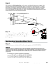
3. “Teach” the New Code to Control Board Memory
A. Press and hold transmitter button.
B. Press and hold the LEARN REMOTE button on
the control board until it beeps.
C. Release transmitter button.
D. Release LEARN REMOTE button. The new code
is stored in control board memory.
+
0
ECE
1 2 3 4 5 6 7 8 9
1 2 3 4 5 6 7 8 9
ECE
A23S 12V
ALKALINE BATTERY
+
0
–
LED