


Product SPecificationS
Product SPecificationS
28 www.goodmanmfg.com SS-CPC90-150
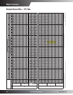
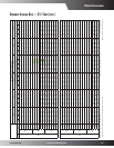
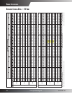
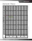
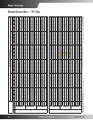
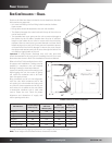
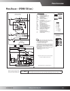
To assist in determining rigging requirements, unit weights are shown to the right.
Note: These weights are calculated without accessories installed.
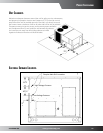
roof curb inStallation — rigging
Provisions for forks have been included in the unit base frame. No other
fork locations are approved.
• Unit must be lifted by the four lifting holes located at the base
frame corners.
• Lifting cables should be attached to the unit with shackles.
• The distance between the crane hook and the top of the unit must
not be less than 60”.
• Two spreader bars must span over the unit to prevent damage to
the cabinet by the lift cables. Spreader bars must be of sucient
length so that cables do not come in contact with the unit during
transport. Remove wood struts mounted beneath unit base frame
before setting unit on roof curb. These struts are intended to protect
unit base frame from fork lift damage. To remove the struts, extract
the sheet metal retainers and pull the struts through the base of the
unit. Refer to rigging label on the unit.
Important: If using bottom discharge with roof curb, duct-work
should be attached to the curb prior to installing the unit. Duct-work
dimensions are shown in Roof Curb Installation Instructions Manual.
Refer to the Roof Curb Installation Instructions
for proper curb installation. Curbing must be
installed in compliance with the National
Roong Contractors Association Manual.
Lower unit carefully onto roof mounting curb.
While rigging the unit, the center of gravity
will cause the condenser end to be lower
than the supply air end.
Bring condenser end of unit into alignment
with the curb. With condenser end of the
unit resting on curb member and using curb
as a fulcrum, lower opposite end of the unit
until entire unit is seated on the curb. When
a rectangular cantilever curb is used, take
care to center the unit. Check for proper
alignment and orientation of supply and
return openings with duct.
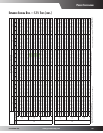
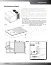
Corner & Center-of-Gravity Locations
30”
Compressor 1
Return
Evaporator Coil
Supply
Compressor 2
49”
Unit Weights
7½-Ton A Models
Weights (lbs)
7½-Ton B Models
& 8½-Ton
Weights (lbs)
10-Ton
Weights (lbs)
12½-Ton
Weights (lbs)
Weight A 280 260 285 420
Weight B 280 245 285 335
Weight C 280 240 285 290
Weight D 280 225 285 230
Shipping Weight 1150 1000 1175 1300
Operang Weight 1110 975 1135 1275