


34
SERVICING INSTRUCTIONS
REPLACING PARTS
13
AR1349
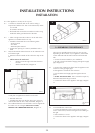
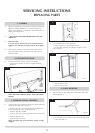
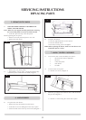
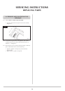
• Replacewithanewelectrode.Donotover-tightenthe
nut; this could break the component
• Replacetheignitionleadbypushingthespadeconnector
onto the terminal (electrode)
14
AR1874
A
B
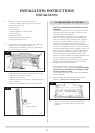
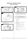
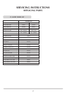
8.4 Pilot Injector
• Undothepilotpipefromthegasvalveandfromthe
underside of the pilot burner, Diagram 14, arrow A
•Removethepipeandtheinjectordropsoutfromthe
burner
8.5 Thermocouple
• Disconnectthethermocouplefromthegas
valve/interrupter, Diagram 14, Arrow B
• Undothethermocouplenutinthebackofthepilot
bracket half a turn. This releases the thermocouple.
Whenreplacingwithanewthermocouple,takecareto
bend the new component to the same shape as the
thermocouple just removed.
To refit the thermocouple into the pilot bracket, ensure it is
pushed fully into the hole. There is a stop on the
thermocouple to set the height.
• Locktheretainingnutjustenoughtogripthe
thermocouple
• Connectthethermocoupletothevalve/interrupterand
take care not to over-tighten
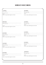
9. IGNITION LEAD
15
AR1872
A
B
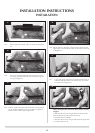
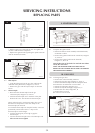
9.1 To replace the ignition lead:
• ReleasetheMainControlAssemblyandtiltbackwards,
see Section 7 above
• Removetheignitionleadfromthecontrolbox,Diagram
15, Arrow A
• Removetheignitionleadfromtheelectrode,
Diagram 15, Arrow B
Note the direction of the lead. The new lead must follow
exactly the same route.
NOTE: THE IGNITION LEAD MUST NOT PASS IN
FRONT OF THE CONTROL BOX AS THIS CAN DAMAGE
THE SENSITIVE ELECTRONICS.
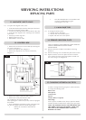
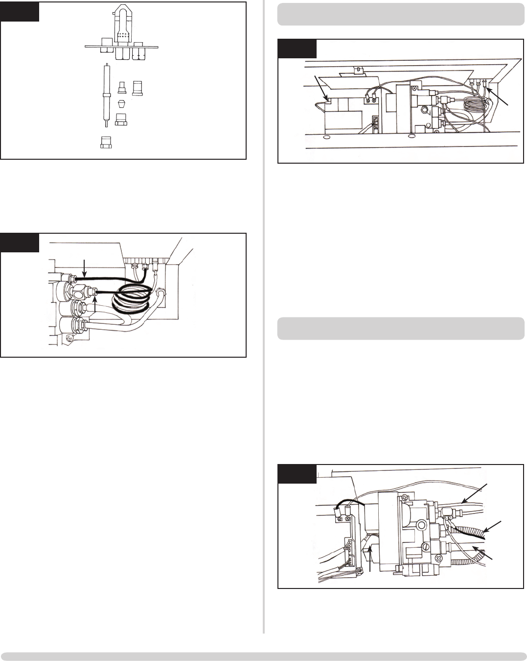
10. GAS VALVE
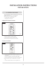
10.1 To change the gas valve:
• Removethecontrolassembly,Section 7
• Releasethegasinletpipe,Diagram16,ArrowA
• Removethethermocouplefromtheinterrupterblock
andreleasethesecondthermocurrentcables •
• Releasethepilotpipe,Diagram16,B
• Releasetheinjectorfeedpipe,Diagram16,C
• Removethewirecable,Diagram16,D
• Removethetwoscrews
The valve can now be freed.
16
AR1873
B
A
C
D