


24
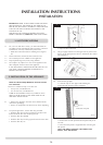
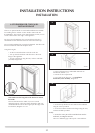
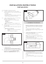
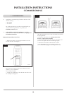
8.2.2 The appliance is factory set for top exit.
8.3 A 152mm (6") diameter hole in the wall or ceiling is
required to install the flue. This can be achieved by either:
a) Core drill
b) Hammer and chisel
• Drillsmallholesaroundthecircumferencewhenusing
method b. Make good both ends of the hole.
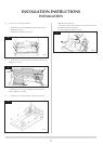
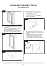
8.4 • Allowenoughroomeitheraboveortothesideofthe
appliance to assemble the flue on top
• Assembleahorizontalflueinthefollowingorder:
-Verticalsection
-90°elbow
-Horizontalplusterminal
• Supporttheopeningofamasonryinstallationwitha
lintel
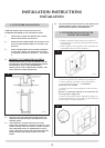
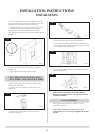
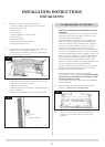
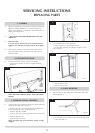
8.5 Onlythehorizontalterminalsectioncanbereducedinsize.
To find the length:
• Measurefromtheoutsideofthewalltothestoponthe
90°
• Add 10 mm to the outlet end
• Measurefromtheedgeoftheslotsclosestto
the wall
• Markaroundtheflue,Diagram31
31
AR0629
10mm
A wall plate is supplied to fix the flue to the wall:
• Bendthetabto90°
• Assembletheplateontothefluebutwaittosecureto
wall and flue after the flue is fully assembled, Diagram 31
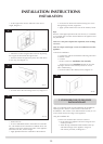
8.6 The cardboard fitment in the terminal is used to support the
flue whilst it is cut to length. ONCE CUT TO SIZE,
REMOVE THE CARDBOARD REMNANT, Diagram 32.
32
AR0630
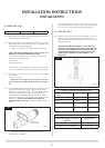
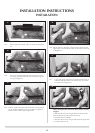
9. ASSEMBLING THE APPLIANCE
There are two possible points of entry for your gas pipe
depending on the location of your appliance, one located
ontheundersideandtheotherlocatedontheleft-hand
side:
• Choosethemostsuitableforyourinstallation
• Slitwithasharpknifebeforebringingthroughthesupply
pipe, Diagram 33
9.1 • Removethecompressionelbowfromtheapplianceand
connect it to the gas supply pipe
As the appliance is fitted into the enclosure:
• Passtheelbowandsupplypipethroughthesilicone
panel
• PURGE THE SUPPLY PIPE. This is essential to expel any
debris that may block the gas controls.
• Connecttheelbowtotheapplianceinletpipe,Diagram
33
33
AR1888
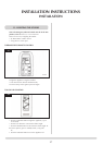
9.2 To reassemble the control unit:
• Puttheleft-handsideofthecontrolunitintotheleft
corner of the interior, before lowering down and sliding to
the right
• Refixwiththe13screws
• Connecttheelbowtotheapplianceinletpipe,Diagram
33
INSTALLATION INSTRUCTIONS
INSTALLATION