


23
INSTALLATION INSTRUCTIONS
INSTALLATION
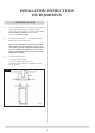
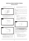
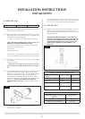
8.1 REAR EXIT FLUE
WALL THICKNESS MIN 200mm MAX 600mm
8.1.3 Remove the flue assembly and terminal guard from the box.
Take care not to lose the fixings.
8.1.4 Having decided on the final appliance position and ensuring
that all external flue terminal clearances are complied with,
(See Section 1, Site Requirements):
• Markthecentreofthefinalfluepositiononthewall
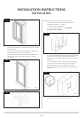
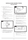
TAKE CARE WHEN MARKING OUT FOR THE FLUE. IT IS
DIFFICULT TO MOVE AFTER INSTALLATION.
A 152mm (6") diameter hole is required to install the flue.
This can be achieved by either:
a) Core Drill.
b) Hammer & Chisel.
It is advisable to drill small holes around the circumference
when using method b). Make good at both ends of the hole.
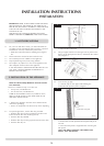
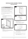
8.1.5 The appliance is factory set for top exit, but can be changed
to a rear exit.
For a rear exit flue:
• Discardtheouterspigotfromthetopexitsetupand
use the replacement spigot supplied in the rear terminal
kit
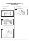
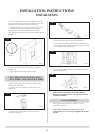
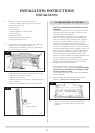
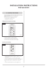
8.1.6 To set the flue length, measure the total wall thickness, then
add 65mm. This total flue length will give the minimum
clearance of 50mm between the rear of the appliance and
the wall. To cut the flue to length using a hacksaw, first
insert the square cardboard fitment into the flue. This will
support the inner flue. Cut through the flue and fitment. See
Diagram 29. ENSURE THE REMAINING FITMENT IS
REMOVED FROM THE FLUE. File the cut edges of the flue
smooth.
29
AR0630
200 mm min
500 mm max
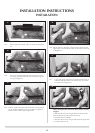
• Fitthefluetotheapplianceandsecurewiththe
aluminium tape supplied
Any terminal which is less than 2 meters above any access
(level ground, balcony or above a flat roof to which people
have access), is to be fitted with the guard supplied.
8.2 TOP EXIT FLUE
8.2.1 There are two types of top exit flues available, one with a
vertical terminal, the other with a horizontal terminal.
Minimum and maximum flue lengths are shown in the Site
Requirements, 2.5.
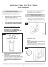
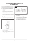
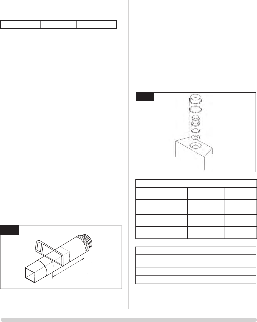
IMPORTANT: WHEN INSTALLING A TOP EXIT FLUE
REFER TO THE TECHNICAL SPECIFICATIONS ON THIS
PAGE FOR THE APPROPRIATE SIZE RESTRICTOR. IF A
RESTRICTOR IS REQUIRED, FIT THIS BETWEEN THE
SMALL OUTLET SPIGOT AND THE AIRDUCT, SEE
Diagram 30.
30
AR0627
TOP EXIT - VERTICAL & HORIZONTAL FLUE
Vertical Flue Height from Top
of Appliance
HorizontalLength Restrictor Size
200 mm 500 mm No restrictor
500 mm 1000 mm No restrictor
1000 mm to 1500 mm 250 mm to 5000
mm
Ø 70 mm
1510 mm to 3000 250 mm to 5000
mm
Ø 60 mm
TOP EXIT - VERTICAL INCLUDING OFFSET
Vertical Flue Height from Top of
Appliance
Restrictor Size
3000 mm up to 4990 mm Ø 52 mm
5000 mm up to 10,000 mm Ø 47 mm