


33
9
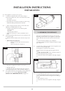
AR1888
10
AR2135
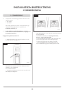
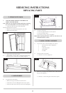
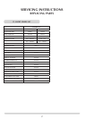
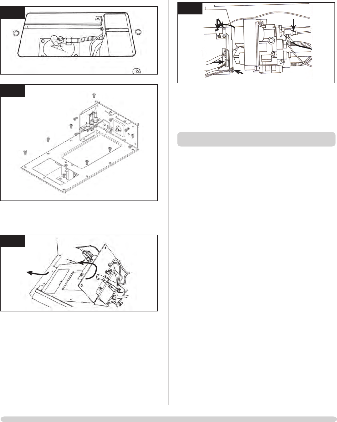
Withallscrewsremoved:
• Slidethecontrolunittotheleft
• Lifttheright-handsideupandout
11
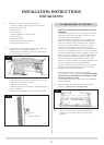
AR2128
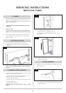
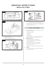
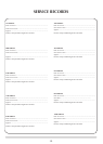
7.4 • Disconnectthetwocablesmarked'A'inDiagram12
12
AR1873
A
B
C
A
• Disconnectthebatteryextensionlead,Diagram12,B
• Disconnectthetouchpadextensionlead,Diagram12,C
The control assembly can now be lifted up and removed.
• Reassembleinreverseorder
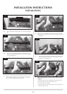
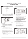
8. PILOT UNIT ASSEMBLY
8.1 The pilot assembly consists of four components which can
be individually changed:
1. Pilot burner bracket
2. Pilot injector
3. Electrode
4. Thermocouple
Before commencing work on the pilot the Main Control
Assembly must be removed, see Section 7 above.
8.2 Pilot Burner Bracket
• Removetheelectrode,seeparagraph8.3
• Removethethermocouple,seeparagraph8.5
• Removethepilotpipe
• Removethetwoscrewssecuringthebracket
The pilot burner bracket can now be removed.
• Replaceinreverseorder
• Checkthepilotgasketandifdamaged,replacewitha
new one
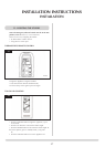
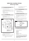
8.3 Electrode
• Pulltheignitionleadofftheelectrodeandundothe
retaining nut, Diagram 13
SERVICING INSTRUCTIONS
REPLACING PARTS