


– 4 –
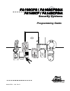
DATA FIELD PROGRAMMING FORM
Entries apply to the FA168CPS/FA168CPSSIA and
FA148CP/FA148CPSIA
controls, except entries shown in dashed boxes, which apply
only to
the FA168CPS
/FA168CPSSIA
(partition entries) and are not applicable to the FA148CP/FA148CPSIA controls
.
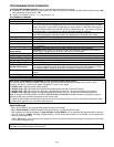
SIA-Compliant Controls: Where noted, certain fields have special settings when used with the FA168CPSSIA and FA148CPSIA SIA-Compliant
controls (indicated by
SIA-Compliant Controls
in reverse type and heavy borders for easy identification).
Entry of a number other than one specified will give unpredictable results. Values shown in brackets are factory defaults.
SIA Guidelines for Non-SIA-Compliant Controls: Notes in certain fields give instructions for programming the FA168CPS/FA148CP for False
Alarm Reduction (these controls can be programmed to reduce false alarms, but they are not fully SIA compliant).
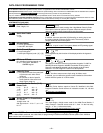
SYSTEM SETUP (
✱
20–
✱
29)
∗
∗∗
∗20
Installer Code
Enter 4 digits, 0-9
| | | [4112]
The Installer Code is used to assign the 4-digit Master Security Code.
The Installer Code can perform all system functions except it cannot
disarm the system unless it was used to arm the system.
∗
∗∗
∗21
Quick Arm Enable
0 = no
1 = yes
[0,0]
Part. 1 Part.2
If enabled, users can press the [#] followed by an arming key to arm
the system instead of using a security code. The security code is
always needed to disarm the system.
∗
∗∗
∗22
RF Jam Option
0 = no RF Jam detection
1 = send RF Jam report
[0]
If enabled, a report is sent if the system detects an RF jamming signal.
UL: must be 1 if wireless devices are used
∗
∗∗
∗23
Quick (Forced) Bypass
0 = no quick bypass
1 = allow quick bypass (code + [6] + [#] )
[0,0]
Part. 1 Part. 2
Zones bypassed by this function will be displayed after the bypass is
initiated.
UL: must be 0
∗
∗∗
∗24
RF House ID Code
00 = disable all wireless keypad use
01–31 = using 5827, 5827BD or
5804BD keypad
| | | [00,00,00]
P1 P2 Common
The House ID identifies receivers and wireless keypads. If a 5827 or
5827BD Wireless Keypad or 5804BD Transmitter is being used, a
House ID code must be entered and the keypad set to the same
House ID. You can assign RF house ID for each partition
∗
∗∗
∗26
Chime By Zone
0 = no (chimes on fault of any entry/exit
or perimeter zone when chime
mode on)
1 = yes (chimes on fault of specific
zones listed in chime zone list 3
when Chime mode on)
[0]
If “yes,” list chime zones on zone list 3 using *81 Menu mode.
If enabled, you can define the specific zones intended to chime when
faulted while the system is in Chime mode.
∗
∗∗
∗27
Powerline Carrier Device (X–10)
House Code
0 = A 6 = G #11 = L
1 = B 7 = H #12 = M
2 = C 8 = I #13 = N
3 = D 9 = J #14 = O
4 = E #10 = K #15 = P
5 = F
[0]
Powerline Carrier devices require a House ID, identified in this field.
Program Powerline Carrier devices in interactive modes ∗79, ∗80 and
∗81.
UL: not for fire or UL installations
∗
∗∗
∗28
Access Code For Phone Module
00 = disable
1st digit: enter 1–9
2nd digit: enter # + 11 for "∗", or # + 12
for "#".
| [00]
(Partition 1 only)
You must assign a 2-digit access code for the 4286 Phone Module, if
used. Example: If desired access code is 7∗, then 7 is the first entry,
and [#] + 11 (for ∗) is the second entry.
NOTE: A 0 in either digit disables the phone module.
UL: must be 00 for UL Commercial Burg. installations
∗
∗∗
∗29 Enable IP/GSM – Communication Device Menu Mode (pass-through programming)
This is a Menu Mode command, not a data field, for programming IP/GSM communication device options. See ∗29 Menu
Mode section later in this document.