


– 24 –
OUTPUT DEVICE PROGRAMMING GENERAL INFORMATION (*79/*80 Menu Mode)
Output Devices: The FA168CPS system supports up to 16 relays and/or Powerline Carrier devices (X-10 devices)
plus 2 built-in trigger outputs in any combination. These 18 “outputs” are assigned to system-wide
output numbers (01-18). Use *79 Menu Mode to assign output numbers and map them to device
addresses.
The FA148CP supports 8 relays and 2 built-in trigger outputs (total 10 outputs).
Output Functions: The system also provides installer-defined output functions, which can be assigned to any of the
physical outputs. Therefore, the action of any one of the outputs can be based on as many of these
defined functions as desired. This lets a single relay or X-10 device perform many functions.
The control supports: FA168CPS = up to 48 defined functions; FA148CP = up to 24 functions
Use *80 Menu Mode to define output functions.
WARNING: Relays and output devices are not recommended for life safety applications.
NOTE: When navigating the *79 and *80 menus: The [
✱
] key is used to accept an entry and advance to the next prompt.
The [#] key is used to revert back to the last question to check or change an entry. Press [
✱
] to go forward again.
Programming Output Devices
1. Use *79 Menu Mode to assign module and output numbers and map them to device addresses.
NOTE: You must map output devices using *79 Menu Mode before you can use *80 menu Mode.
2. Use *80 Menu Mode to create output definitions, which control the output devices, if desired.
3. Use *81 Zone List Menu mode to define zone lists for use with output devices if the device action is based on more than
one zone.
• To program a device for manual activation (user code + [#] [7] / [#] [8] + 2-digit device number) or for scheduled automatic
activation, simply map the device using *79 Menu mode.
• To program a device to automatically activate upon a system event (or function key), use *79 Menu mode to map the device,
then use *80 Menu mode to define the automated device action.
∗
∗∗
∗79 RELAY/POWERLINE CARRRIER DEVICE (X-10) PROGRAMMING MENU MODE
(press
∗
∗∗
∗
79 while in Programming mode) The *79 Device Mapping Worksheet is on page Error! Bookmark not defined..
Use this menu to assign Relay Module device addresses and specific relay numbers, and Powerline Carrier unit numbers. The
system is based on predefined module addresses for 4204 and 4229 modules. Refer to the table shown at the “Module
Address” prompt on the next page and set the modules’ addresses (via module DIP switches) accordingly.
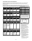
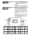
The following table shows how these outputs are identified.
Output Identification
This output… is identified by…
Relays the Relay Module’s device address and the relay position on that module (i.e. the physical relay
number, 1-4, on that module).
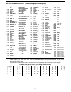
X-10 Device a house ID (entered in data field *27) and the unit number of the device.
Built-in Outputs the output number assigned, 17 for Trigger 1 and/or 18 for Trigger 2.
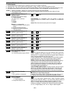
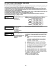
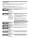
ENTER OUTPUT NO.
00 = QUIT xx
Device Output Number
FA168CPS:
01-16 = relays/X-10
17, 18 = on-board triggers
FA148CP:
01-08 = relays/X-10
17, 18 = on-board triggers
[∗] to continue
00 to quit
This is the logical (or reference) relay number as used in the
system. Relays and X-10 devices are numbered 01-16; the on-
board triggers are numbered 17 and 18 and can be programmed
for inverted output, if required.
17 OUT NORM LOW
0 = NO 1 = YES 0
Output Normally Low
0 = no (standard default)
1 = yes
[∗] to continue
(prompt appears only for Triggers 17 and 18)
Selecting
0
(no) sets the output level normally high (default
setting).
Selecting
1
(yes) sets the output normally low.
Output Trigger 17 can be used for resetting 4-wire smoke
detectors by connecting it to the negative power terminal of the
smoke detector, selecting 1 at this prompt, and setting as zone
type 54, fire zone reset, in *80 Menu mode.
After entry, display returns to Output Number prompt. Use *80
Menu mode to program the function of the trigger.