


9
ENVISION RESIDENTIAL INSTALLATION MANUAL
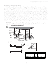
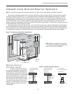
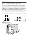
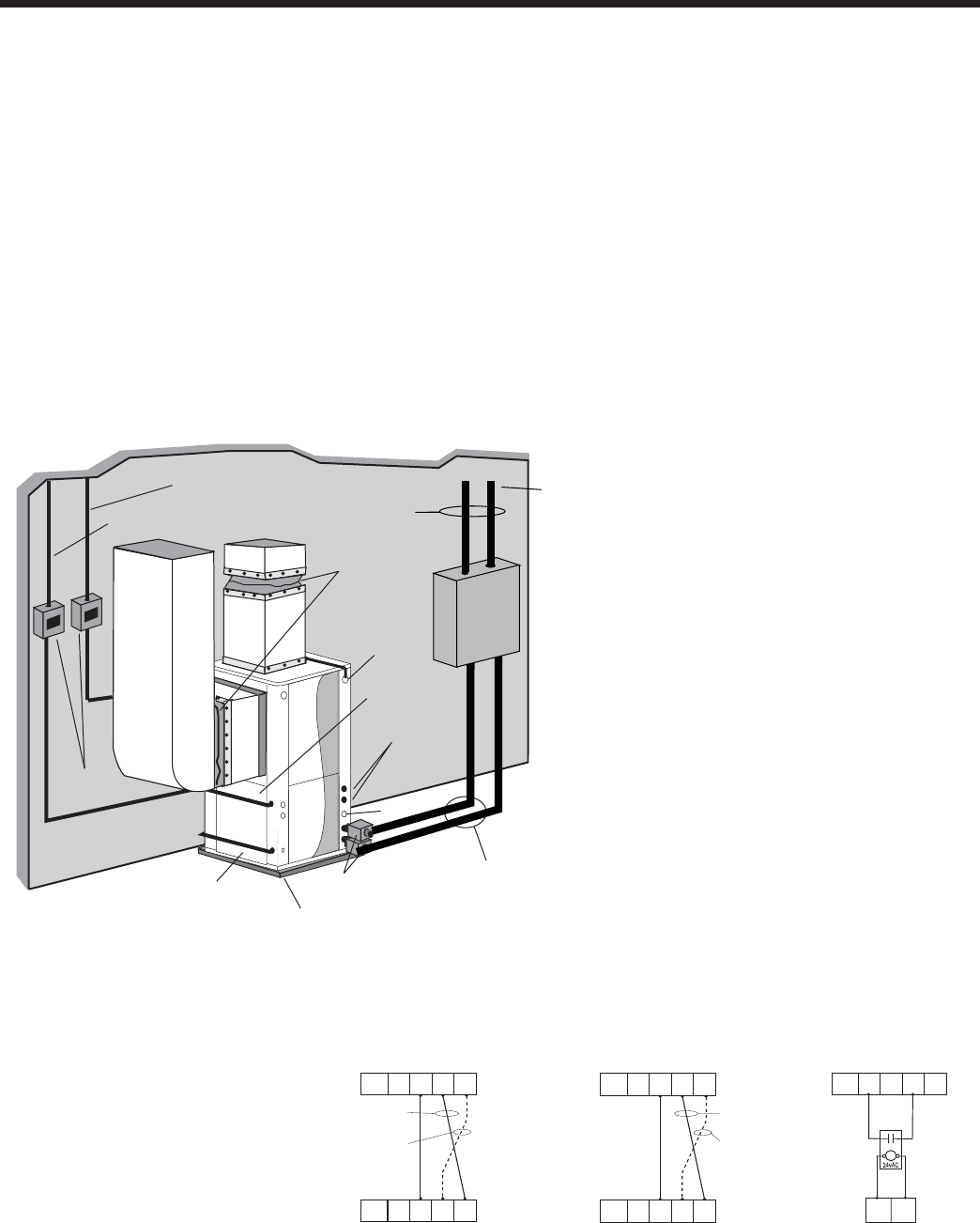
Figure 7: Closed Loop Ground Source Application
Closed Loop Ground Source Systems
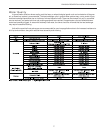
Note: For closed loop systems with antifreeze protection, set SW2-2 to the “loop” position (see table on page 28).
Once piping is completed between the unit, pumps and the ground loop (see fi gure below), fi nal purging and charging
of the loop is required. A fl ush cart (or a 1.5 HP pump minimum) is needed to achieve adequate fl ow velocity in the loop
to purge air and dirt particles from the loop itself. Antifreeze solution is used in most areas to prevent freezing. Flush the
system adequately to remove as much air as possible then pressurize the loop to a static pressure of 40-50 PSI (summer)
or 50-75 PSI (winter). This is normally adequate for good system operation. Loop static pressure will fl uctuate with the
seasons. Pressures will be higher in the winter months than during the cooling season. This fl uctuation is normal and should
be considered when initially charging the system.
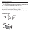
After pressurization, be sure to open the plug 1 turn in the end of the loop pump motor(s) (if applicable) to allow trapped
air to be discharged and to ensure that the motor housing has been fl ooded. Ensure that the loop pumps provide adequate
fl ow through the unit(s) by checking the pressure drop across the heat exchanger and comparing it to the unit capacity data
in the specifi cation catalog. 2.5 to 3 GPM of fl ow per ton of cooling capacity is recommended in earth loop applications.
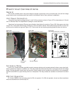
Multiple Units on
One Flow Center
When two units are connected to
one loop pumping system, pump control is
automatically achieved by connecting the
SL terminals on connector P2 in both units
with 2-wire thermostat wire. These terminals
are polarity dependant (see Figure 8). The
loop pump(s) may be powered from either
unit, whichever is more convenient. If either
unit calls, the loop pump(s) will automati-
cally start. The use of two units on one fl ow
center is generally limited to a total of 20
GPM capacity.
Envision to
Electromechanical Units
Shut
Down
CC
SL1
In
SL1
Out
Envision Unit #1
To Electromechanical Unit
C
S
Shut
Down
CC
Shut
Down
CC
SL1
In
SL1
Out
SL1
In
SL1
Out
Single Speed
Envision Unit #1
With pump
wired to Unit 1
With pump
wired to
Unit 2
Envision to Envision
Microprocessor Units
Envision Unit #2
Single Speed
With pump
wired to Unit 1
With pump
wired to
Unit 2
Shut
Down
CC
Shut
Down
CC
SL1
In
SL1
Out
SL1
In
SL1
Out
Dual Capacity
Envision Unit #1
Envision Unit #2
Dual Capacity
Envision to Envision
Microprocessor Units
Figure 8: Primary/Secondary Hook-up
Flexible Duct
Collar
Vibration Absorbing Pad
P/T Plugs
Drain
Desuperheater
Connections
Auxiliary
Heater
Knockout
Low
Voltage to
Thermostat
Unit Supply
Auxiliary Heat
Supply
Insulated piping
or hose kit
Disconnects
(If Applicable)
Unit Power
P/T
TO
LOOP
Ge
o
Link
®
Flow
C
e
nt
e
r
GeoLink
®
Polyethylene w/
Armaflex
®
Insulation
Note: Additional information can be found
in Flow Center installation manual (IM1961)
and Flush Cart manual (WFS302).