


6
ENVISION RESIDENTIAL INSTALLATION MANUAL
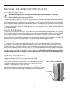
Duct System
An air outlet collar is provided on vertical top air discharge units and all horizontal units to facilitate a duct connection
(vertical bottomfl ow units have no collar). A fl exible connector is recommended for discharge and return air duct connec-
tions on metal duct systems. Uninsulated duct should be insulated with a minimum of 1-inch duct insulation. Application of
the unit to uninsulated ductwork in an unconditioned space is not recommended as the unit’s performance will be adversely
affected.
If the unit is connected to existing ductwork, check the duct system to ensure that it has the capacity to accommodate
the air required for the unit application. If the duct is too small, as in the replacement of heating only systems, larger duct-
work should be installed. All existing ductwork should be checked for leaks and repaired if necessary.
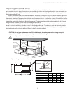
The duct system should be sized to handle the design airfl ow quietly and effi ciently. To maximize sound attenuation of
the unit blower, the supply and return plenums should include an internal duct liner of fi berglass or constructed of ductboard
for the fi rst few feet. On systems employing a sheet metal duct system, canvas connectors should be used between the unit
and the ductwork. If air noise or excessive airfl ow is a problem, the blower speed can be changed.
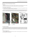
Water Piping
The proper water fl ow must be provided to each unit whenever the
unit operates. To assure proper fl ow, use pressure/temperature ports
to determine the fl ow rate. These ports should be located at the supply
and return water connections on the unit. The proper fl ow rate cannot
be accurately set without measuring the water pressure drop through
the refrigerant-to-water heat exchanger.
All source water connections on commercial units are fi ttings that
accept a male pipe thread (MPT). Insert the connectors by hand, then
tighten the fi tting with a wrench to provide a leakproof joint. When con-
necting to an open loop (groundwater) system, thread any copper MPT
fi tting into the connector and tighten in the same manner as described
above.
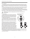
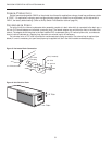
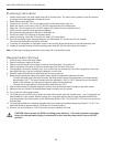
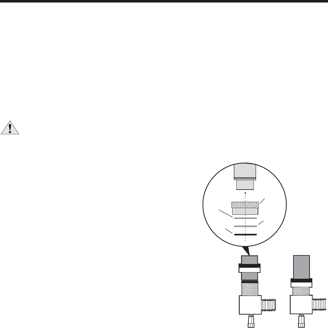
All source water connections on residential units are swivel piping
fi ttings (see Figure 4) that accept a 1-inch male pipe thread (MPT) .
The swivel connector has a rubber gasket seal similar to a rubber hose
gasket, which when mated to the fl ush end of any 1-inch threaded pipe
provides a leak-free seal without the need for thread sealing tape or
compound. Check to ensure that the rubber seal is in the swivel con-
nector prior to attempting any connection. The rubber seals are shipped
attached to the waterline. To make the connection to a ground loop sys-
tem, mate the brass connector (supplied in CK4L connector kit) against
the rubber gasket in the swivel connector and thread the female locking
ring onto the pipe threads, while maintaining the brass connector in the
desired direction. Tighten the connectors by hand, then gently snug the
fi tting with pliers to provide a leak-proof joint. When connecting to an open loop (ground water) system, thread any 1-inch
MPT fi tting (SCH80 PVC or copper) into the swivel connector and tighten in the same manner as noted above. The open
and closed loop piping system should include pressure/temperature taps for serviceability.
Never use fl exible hoses smaller than 1-inch inside diameter on the unit. Limit hose length to 10 feet per connection.
Check carefully for water leaks.
Figure 4: Swivel Connections
(Residential Units)
Locking
Ring
Stainless
Steel
Snap Ring
Gasket
Support
Sleeve
Gasket
Material
CAUTION: Be sure to remove the shipping material from the blower discharge before con-
necting ductwork.