


24
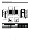
ENVISION RESIDENTIAL INSTALLATION MANUAL
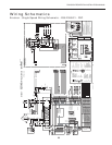
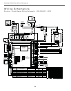
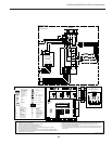
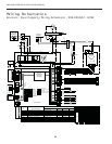
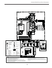
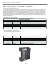
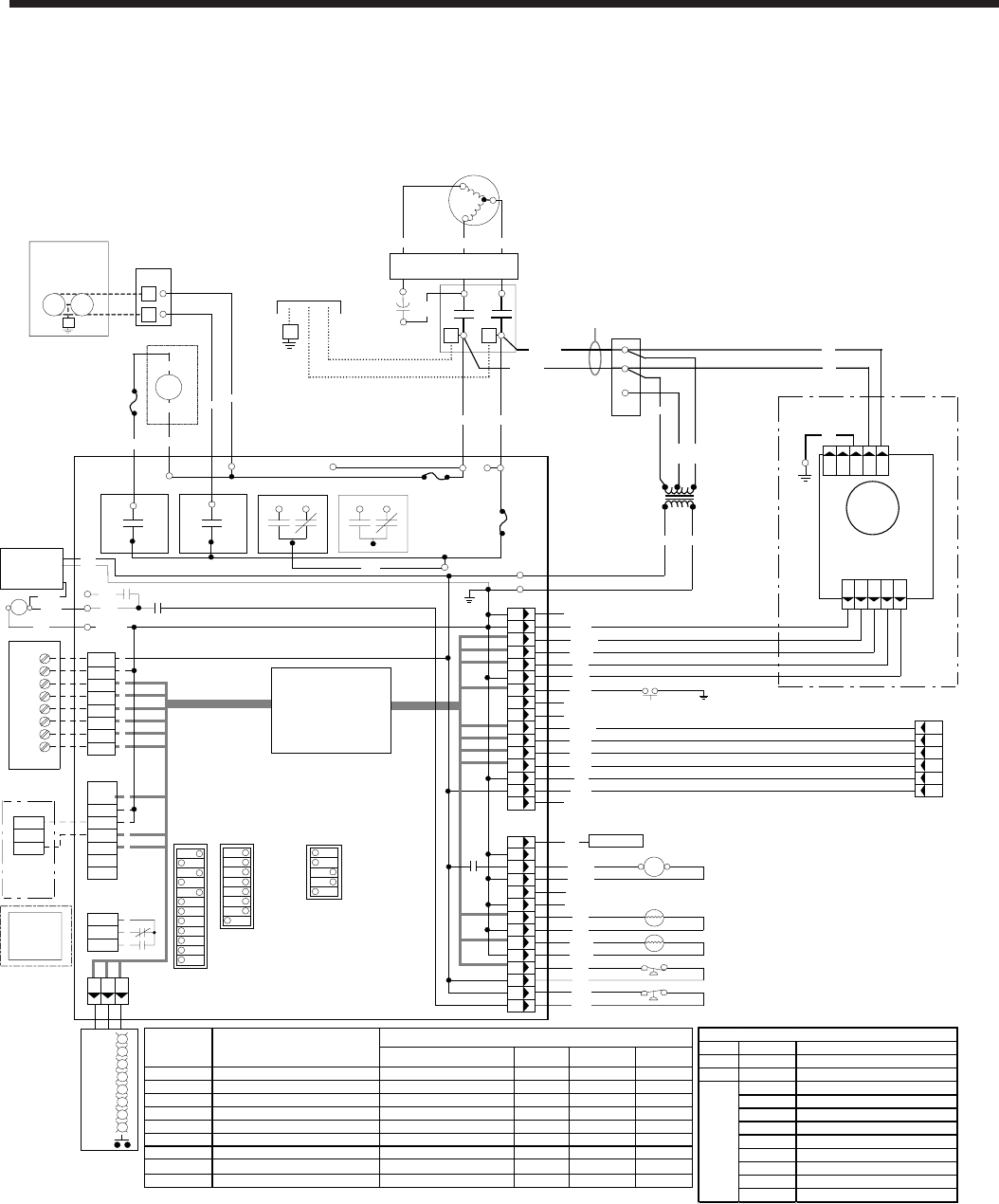
Wiring Schematics
Envision - Single Speed Wiring Schematic - 208-230/60/1 - ECM
C
HWL
HP
Thermostat
CO
R
C
Y1
O
L1
Y2
NOTE 4
G
LP
PS
FP
W
Brn(15)
Org(14)
1
2
3
P10
4
5
97P774-01 6/29/06
Org
Brn
NOTE 2
6
Blk/Wht(11)
Gry/Wht(10)
SL1 In
SL1 Out
Optional
Remote Unit
Without
Loop Pump
Status LED PCB
SW4
R
R
R
R
R
G
Y
R
T
T
CC
Blk(1)
Transformer
NOTE1
24V
Red
208V
Blu
240V
Blk
Blk/WhYel
Gry(9)
Unit Power
208-230/60/1
G
L2 L1
CC
NOTE 6
DHW
Pump
Blu
3A
Fuse
Optional
Electronic
Air-Filter
NOTE 10
240V L2
240V L1
240V L2
P6
Premier 2
Microprocessor
Logic Control
(DC Voltage)
P1
FusedL2
R
C
CC-GND
NO
CR2
COM
F1-10A 240V
FusedL2
NO
CR1
COM
Pink
1
2
3
4
5
6
7
8
1
2
3
P4
Pink
Black
Violet
Yellow
Black
Blue
Blue
Orange
Orange
Pink
Yellow
Yellow
Pink
Orange
White
Tan
Blue
Not Used
1
2
3C
P2
Down
C
1
2
3
4
5
6
7
Shut
SL1 In
Not
SL1 Out
Used
NOTE 3
Acc Com
Acc NC
Acc NO
1
2
3
P3
Not Used
Not Used
Brown
Gray
123
F1-10A
240V
Tan
Not Used
Red
6
5
4
8
7
P5
12
1
2
9
10
3
4
9
11
2
10
8
1
12
5
3
13
14
15
16
11
G
W
O
R
C
Y1
Y2
LO
On
SW1
1
2
3
4
5
6
7
8
9
10
11
12
On
SW2
1
2
3
4
5
6
7
8
No Htg3 / Htg3
Dehum / Norm
Fan / Comp
Loop / Well
Test / Norm
Outputs / Norm
Inputs / Norm
ECM2
Air Flow
Settings
NOTE 7
Black
Blue
14
13
6
7
CC
NO
NC
CR4 COM
NO
NC
CR3 COM
FusedL1
Blk(7)
Blu(17)
Violet(2)
RV
Ext Pump
1/2 hp Total
208-230/60/1
Pump Pump
G
2
1
PB1
1
2
Yel(8)
Comfort
Alert
R
Y
C
CCHI
Not Used
Not Used
Violet(3)
Blk(5)
Yel(6)
L
Comfort Alert
Pulse L / Constant L
(See Note 9)
ECM2
Fan Motor
Grn
15 10163
On/Off
PWM
RPM
C2
RPM grnd
P12
P112 3 4 51
8
Pink(13)
NOTE11
C
S
R
Run
Capacitor
1
3
2
Red Black
Blue
Tan
(16)
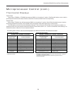
Comfort Alert
Field Selection Dips- #1 On, #6 On, #7On
Drain pan overflow Lockout
FP thermistor(loop<15°F,well<30°F)Lockout
High Pressure> 600 PSI Lockout
Low Pressure< 40 PSI Lockout / CA
ECM2 RPM< 100 rpm Lockout
Microprocessor malfunction*
HWL thermistor> 130°F
DHW pump switch off
Drain
Water Flow
High Press
Low Press/Comp
Air Flow
Status
DHW Limit
DHW off
LED Normal Display Mode
#1 Off,#6 On, #7 On
Drain pan overflow
FP thermistor(loop<15°F, well<30°F)
High Pressure> 600 PSI
Low Pressure< 40 PSI / CA
ECM2 RPM< 100 rpm
Not Used
HWL thermistor> 130°F
DHW pump switch off
Current Fault Status
#6 Off, #7 On
Y1
Y2
O
G
W
SL1
--
--
Inputs
#6 On,#7 Off
Compressor Lo
Compressor Hi
RV
FAN
DHW Pump
Loop Pump(s)
--
--
Outputs
#6 Off, #7Off
Blower Lo
Blower Med
Blower Hi
Aux Heat#1
Aux Heat#2
AuxHeat#3
Aux Heat#4
--
Outputs2
Diagnostic Modes
*Green LED not flashing
LED Flash Code Description
Green Solid ModuleHas Power
Red Solid Compressor Overload Trip
Code 1 Long Run Time
Code2 System PressureTrip
Code 3 Short Cycling
Code 4 Locked Rotor
Code 5 Open Circuit
Code 6 Open Start Circuit
Code 7 Open Run Circuit
Code 8 Welded Contactor
Code 9 Low Voltage
Yellow
Comfort Alert Status
PN - 17P513-07
On
SW3
2 Speed /1 Speed
Normal / Finish on2
nd
(Note 12)
No RPM / RPM
Old EH & ECM / Normal (Note 8)
Envision / E Series or Premier
1
2
3
4
5