


5
ENVISION RESIDENTIAL INSTALLATION MANUAL
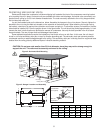
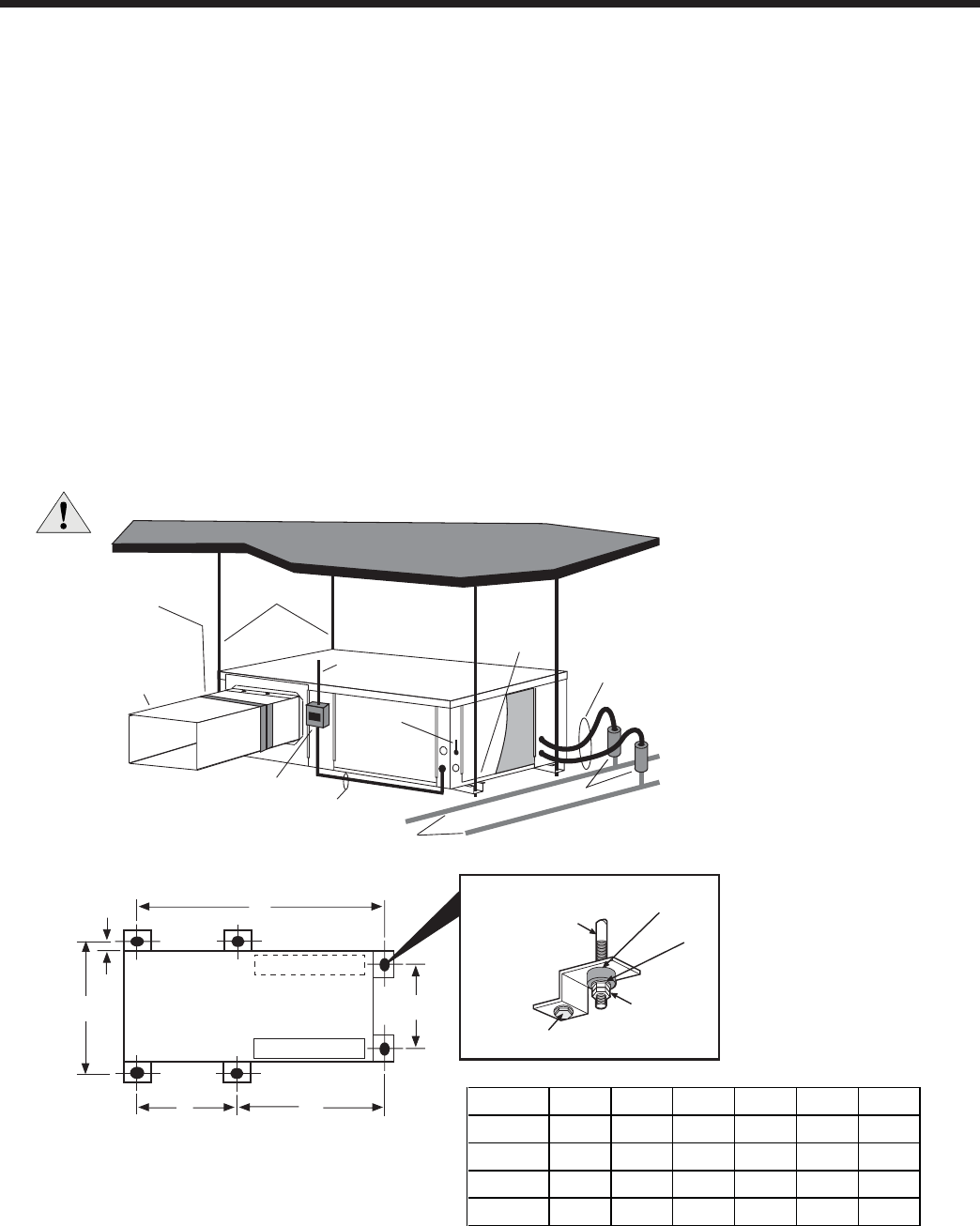
Installing Horizontal Units
Remove and discard the compressor hold down shipping bolt located at the front of the compressor mounting bracket
prior to setting the unit in place. Horizontal units are available with side or end discharge. Horizontal units are normally sus-
pended from a ceiling by six 3/8-inch diameter threaded rods. The rods are usually attached to the unit by hanger bracket
kits furnished with each unit.
Lay out the threaded rods per the dimensions below. Assemble the hangers to the unit as shown. Securely tighten the
brackets to the unit using the weld nuts located on the underside of the bottom panel. When attaching the hanger rods to
the bracket, a double nut is required since vibration could loosen a single nut. To allow fi lter access, one bracket on the fi lter
side should be installed 180° from the position shown in the fi gure below. The unit should be pitched approximately 1/4-inch
towards the drain in both directions to facilitate the removal of condensate. Use only the bolts provided in the kit to attach
hanger brackets. The use of longer bolts could damage internal parts.
Some residential applications require the installation of horizontal units on an attic fl oor. In this case, the unit should
be set in a full size secondary drain pan on top of a vibration absorbing pad. The secondary drain pan prevents possible
condensate overfl ow or water leakage damage to the ceiling. The secondary drain pan is usually placed on a plywood base
isolated from the ceiling joists by additional layers of vibration absorbing material.
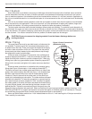
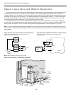
Insulate supply
plenum and use
at least one 90
elbow to
reduce noise
Electrical
Disconnect
Flexible Duct
Collar
Threaded Rods
Line Voltage
Ball Valves
Hose
Kits
To Line
Power
To
Thermostat
Hanging
Brackets
(Included)
Building Water Loop
O
Figure 2: Horizontal Unit Mounting
CAUTION: Do not use rods smaller than 3/8-inch diameter since they may not be strong enough to
support the unit. The rods must be securely anchored to the ceiling.
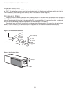
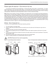
Figure 3: Hanger Location and Assembly
C
F
B
Air Coil
Air Coil
D
E
A
Vibration Isolator
Washer
Hex Nuts
(not supplied)
Bolt and
Lockwasher
3/8
Threaded Rod
(not supplied)
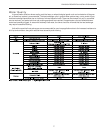
Model A B C D E F
022 - 030 24.8
27.8
27.8
27.8
63.4 21.1 38.1
25.3
1.1
036 - 038 72.4 24.1 43.1
29.3
1.1
042 - 049 77.4 24.1 48.1
29.3
1.1
060 - 072 82.4 24.1 53.1
29.3
1.1