


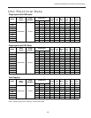
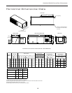
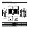
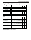
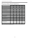

23
ENVISION RESIDENTIAL INSTALLATION MANUAL
C
HWL
HP
Thermostat
CO
R
C
Y1
O
L1
Y2
NOTE 4
G
LP
PS
FP
W
Brn(15)
Org(14)
1
2
3
P10
4
5
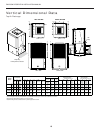
Envision - Single Speed Wiring Schematic - 208-230/60/1
97P774-06 9/27/06
PB2
Auxiliary Electric Heat Power
208-230/60/1
With optional ' EA' Series
Auxiliary ElectricHeat
Typical schematic shown
2
3
HE1 TS1
HE2 TS2
HE3 TS3
HE4 TS4
P7
L4 L2
L2 NOTE 5
Pink
Yel
Blk
Gray
Pink
Yel
Blk
Gray
Gray
Blk
Yel
Pink
Gray
Pink
Blk
Yel
Pink
Yel
Blk
Gray
Pink
Yel
Blk
Gray
Grn
F2
P9
ER1
ER2
ER3
ER4
L1
L1 L3
NO
NO
NO
NO
Org
Brn
Brn
Org
Brn
Or
5
4
Pink
Orange
White
Tan
Blue
NOTE 2
Red
6
EA Series PCB
Blk/Wht(11)
Gry/Wht(10)
SL1 In
SL1 Out
Optional
Remote Unit
Without
Loop Pump
Foldandmatearrows
Fold and mate arrows
Fold and mate arrows
Fold and mate arrows
L1 L2
Single Disconnect Power
208-230/60/1
Aux ElectPower
208-230/60/1
L1 L2 L1 L2
UnitPower
208-230/60/1
CSA installed unitsonly
Local codes may require a single
source of power supply
Breaker box
furnished by
installer
E-Series Logic Board- Physical Layout
NOTE 9
1
123
P10
456
P2
1
Status LED PCB
SW4
R
R
R
R
R
G
Y
R
T
T
G G
4
3
2
1
P8
1
2
3
4
123
1
P4
OnOff
SW1
240V - L2
240V - L1
Fused L2
Fused L2
Fused L2
F1
F1
R
R
Microprocessor
Premier 2 Logic Board
CR2- Loop
Pump
N.O.
240V - L2
240V - L1
C
C
1
2
3
4
5
6
7
8
9
10
11
12
13
14
15
16
P6
1
2
3
4
5
6
7
8
9
10
11
12
13
14
P5
Fused L2
Fused L1
CR1- DHW
Pump
N.O.
CC
CC-GND
CCLO
CCHI
123
P3
2
3
4
5
6
7
8
9
10
11
12
1
OnOff
SW2
2
3
4
5
6
7
8
1
OnOff
SW3
2
3
4
5
P1
12345678
2
345
P2
671
RCY1Y2 GOWL
Shut
Down
ACC
NO
ACC
NC
ACC
COM
CC
SL1
IN
SL1
Out
SL2
IN
SL2
Out
Circuit Breakers
CC
Blk(1)
Transformer
NOTE1
24V
Red
208V
Blu
240V
Blk
Blk/WhYel
Gry(9)
N.O.
CR4-
Com
N.O.
CR3-
Com
N.C.
Unit Power
208-230/60/1
G
L2 L1
CC
NOTE 6
DHW
Pump
Blu
3A
Fuse
Optional
Electronic
Air-Filter
NOTE 10
240V L2
240V L1
240V L2
P6
Premier 2
Microprocessor
Logic Control
(DC Voltage)
P1
FusedL2
R
C
CC-GND
NO
CR2
COM
F1-10A 240V
FusedL2
NO
CR1
COM
Pink
1
2
3
4
5
6
7
8
1
2
3
P4
Pink
Black
Violet
Yellow
Black
Blue
Blue
Orange
Orange
Pink
Yellow
Yellow
Pink
Orange
White
Tan
Blue
Not Used
1
2
3C
P2
Down
C
1
2
3
4
5
6
7
Shut
SL1 In
Not
SL1 Out
Used
NOTE 3
Acc Com
Acc NC
Acc NO
1
2
3
P3
Not Used
Not Used
Brown
Gray
123
Main Logic PCB
F1-10A
240V
Tan
Not Used
Red
6
5
4
8
7
P5
12
1
2
9
10
3
4
9
11
2
10
8
1
12
5
3
13
14
15
16
11
G
W
O
R
C
Y1
Y2
LO
On
SW1
1
2
3
4
5
6
7
8
9
10
11
12
ECM2
Air Flow
Settings
Black
Blue
14
13
6
7
CC
NO
NC
CR4
COM
NO
NC
CR3
COM
Blk(7)
Blu(17)
Violet(2)
RV
Ext Pump
1/2 hp Total
208-230/60/1
Pump Pump
G
2
1
PB1
1
2
Yel(8)
Comfort
Alert
R
Y
C
CCHI
Not Used
Not Used
Violet(3)
Blk(5)
Yel(6)
L
Comfort Alert
15
10
16
3
P12
P11
2
3
4
5
1
8
Pink(13)
Field Selection Dips- #1 On, #6 On, #7 On
Drain pan overflow Lockout
FP thermistor (loop<15°F,well<30°F) Lockout
High Pressure >600 PSI Lockout
LowPressure< 40 PSI Lockout
ECM2 RPM < 100rpm Lockout
Microprocessor malfunction *
HWL thermistor > 130°F
DHW pump switch off
Drain
Water Flow
High Press
Low Press / Comp
Air Flow
Status
DHW Limit
DHW off
LED Normal Display Mode
#1 Off, #6 On,#7 On
Drain pan overflow
FP thermistor (loop<15°F, well<30°F)
High Pressure > 600PSI
LowPressure< 40 PSI
ECM2 RPM < 100 rpm
Not Used
HWL thermistor > 130°F
DHW pump switch off
Current Fault Status
#6 Off, #7 On
Y1
Y2
O
G
W
SL1
SL2
--
Inputs
#6 On, #7 Off
Compressor Lo
Compressor Hi
RV
FAN
DHW Pump
Loop Pump 1
Loop Pump 2
--
Outputs
#6 Off, #7 Off
Blower Lo
Blower Med
Blower Hi
Aux Heat #1
Aux Heat #2
AuxHeat #3
Aux Heat #4
--
Outputs2
Diagnostic Modes
*Green LED not flashing
NOTE11
C
S
R
Run
Capacitor
1
3
2
Red Black
Blue
Tan
(16)
Comfort Alert
LED Flash CodeDescription
Green Solid ModuleHas Power
Red Solid Y1 PresentButCompressor NotRunning
Code 1 Long Run Time
Code2 SystemPressureTrip
Code 3 ShortCycling
Code 4 Locked Rotor
Code 5 Open Circuit
Code 6 Open StartCircuit
Code 7 Open RunCircuit
Code 8 Welded Contactor
Code 9 Low Voltage
Yellow
Comfort Alert Status
Notes:
1 – Switch Blue and Red wires for208V operation.
2 - Connection of remote unit that does not have a loop pumpfor slave operation.
3 - 24V Accessoryrelay (see SW2 - 3 for description ofoperation )
4 - The blk/wh andgray/wh wires are removed when Aux Heat is installed .
6 - DHWpump onlyin models with hot water generation option.
5 - Buss lugs L1and L2 can be removed and dual power wire sets connected directly to box lugsL1, L2 ,
and L3, L4.
10 - When optional electronicair -filter is installed,power for the electronic air-filterispr ovided by P2-2 and
24 VAC.
8 – SW3-4 should be in the OF F position when usingthe17P501A01 electric heat board and
should be ON when using the17P514A01 electri c heat board .
11- Comfort Alert fault output to Premier Control Board
9 – SW2- 8 must be in the OFFposition for pulsed “L” lockout signal and in the ON position for constant
“L” lockout signal .
7 – This Switch allows the unit todown stage with thet-stat when OFF and finish on secondstage when
ON.Fini sh second stage reduc es stage changing in recip dual capacity compressor s and should
be ON for unzoned Dual Cap E -Series or Premier2 speed units.
On
SW3
On
SW2
1
2
3
4
5
6
7
8
No Htg3 / Htg3
Dehum / Norm
Fan / Comp
Loop / Well
Test / Norm
Outputs / Norm
Inputs /Norm
2 Speed / 1 Speed
Normal / Finish on2
nd
(Note 7)
No RPM / RPM
Electric Heat/ Normal (Note 8)
Envision / E Series or Premier
1
2
3
4
5
Pulse L / Constant L(NOTE 9)
Y
L
R
C
DC
Sol
Data
Port
Comfort Alert
Physical Layout
POWER
ALERT
TRIP
Brn
Wht
Grn
P13
H M L
PSC
Fan Motor
Cap
Blk
Wht
Thermistor
Lightemitting diode - Green
Relay coil
Capacitor w/ bleed resistor
Switch - Condensate overflow
Switch - High pressure
Switch - Low pressure
Switch -HotWater On/Off
Polarized connector
Factory Low voltage wiring
Factory Line voltage wiring
Field low voltage wiring
Field line voltage wiring
Optional block
DC Voltage PCB traces
Internal junction
Quick connectterminal
Wire nut
Fieldwirelug
Ground
Fuse
CC -
CO -
CR1 -
CR2-
CR3 -
CR4 -
F1 and F2 -
FP -
HE -
HP -
LP -
PB1, PB2 -
PS -
RV -
SW1 -
SW2 -
SW3 -
SW4 -
TS -
Compressor Contactor
Condensate overflow sensor
DHW pump relay
Loop pump relay
Fuses
Freeze protection sensor
Heater element
High pressure switch
Lowpressure switch
Power blocks
Power strip
Reversing Valve coil
DIP package 12 position
DIP package 8 position
DIP package 5 position
Hot water pump enable switch
Thermal limit switch
Legend
Relay Contacts-
N.O., N.C.
G
T
132
P
L1
PSC Fan Speed Relay
PSC Fan Power Relay
ER1 to ER4 - Aux heat stage relays
HWL -
Hot water limit sensor
SC -
Start Contactor
Start Relay
SR -
CS - Compressor Solenoid
CA -
Comfort Alert
Wiring Schematics
Envision - Single Speed Wiring Schematic - 208-230/60/1 - PSC