30
ENVISION RESIDENTIAL INSTALLATION MANUAL
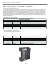
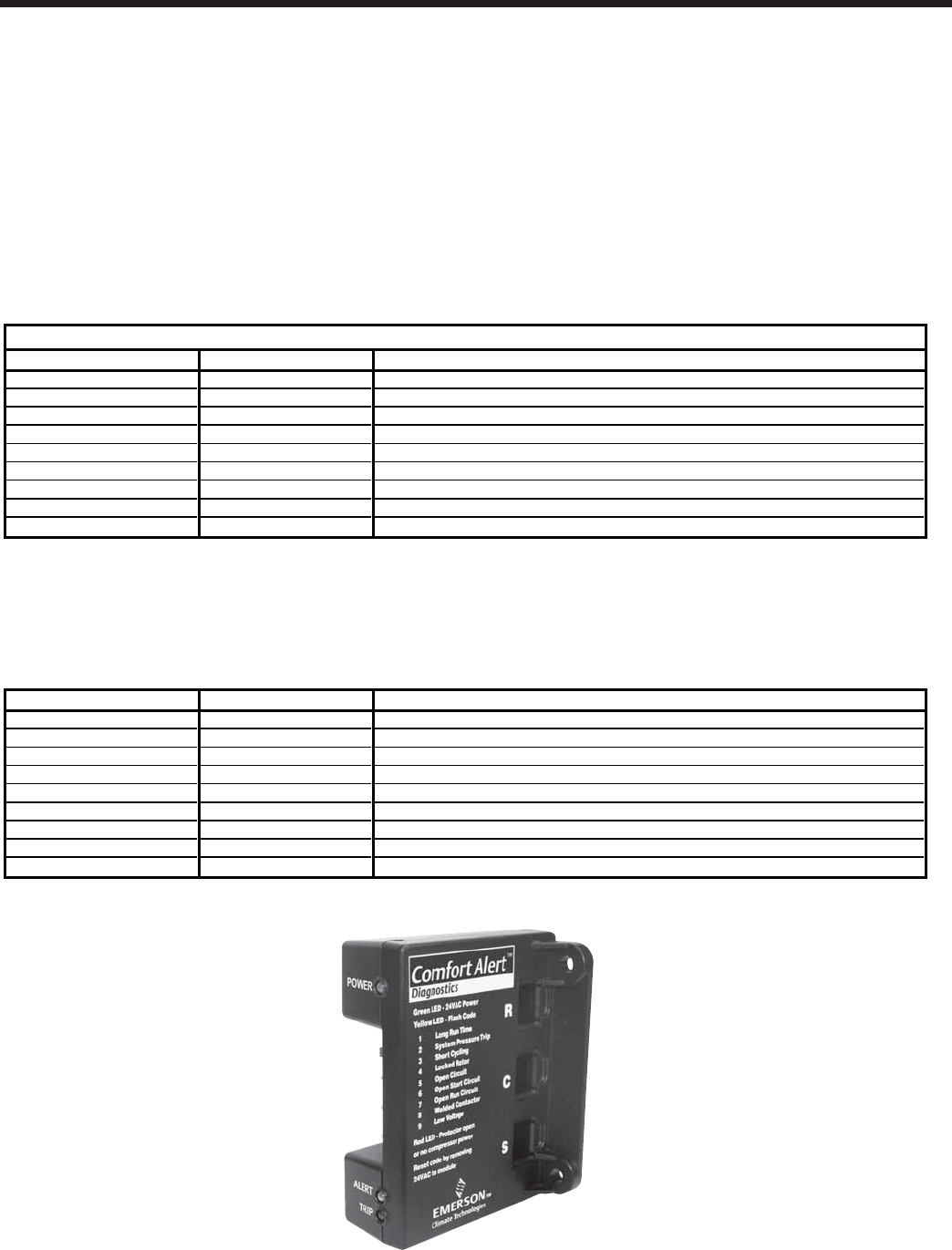
Green "POWER" LED - module has power
Red "TRIP" LED - Thermostat "Y" demand signal is present, but the compressor is not running.
Yellow "ALERT" LED LED Description Cause
Flash Code 1 Long Run Time Eighteen consecutive hours of compressor run time
Flash Code 2 System Pressure Trip Not applicable
Flash Code 3 Short Cycling Compressor run time of less than 3 minutes on 4 consecutive cycles
Flash Code 4 Locked Rotor Four consecutive compressor protector trips indicating compressor won't start
Flash Code 5 Open Circuit "Y" thermostat demand signal with no compressor current
Flash Code 6 Open Start Circuit "Y" thermostat demand signal with no current in the start circuit
Flash Code 7 Open Run Circuit "Y" thermostat demand signal with no current in the run circuit
Flash Code 8 Welded Contactor Current detected with no "Y" thermostat demand signal present
Flash Code 9 Low Voltage Less than 17 VAC detected in control circuit
* Flash code number corresponds to a number of LED flashes, followed by a pause and then repeated.
* TRIP and ALERT LEDs flashing at the same time indicates control circuit voltage is too low for operation.
* Reset ALERT flash code by removing 24 VAC power from module.
* Last ALERT flash code is displayed for 1 minute after module is powered on.
Resetting Comfort Alert Codes
Alert codes can be reset manually by cycling power off and on to the Comfort Alert module. Alert codes will reset automatically if
conditions return to normal.
Flash Code Number LED Description Automatic Reset of Alert Codes
Flash Code 1 Long Run Time Thirty "alert free" on and off cycles to reset automatically
Flash Code 2 System Pressure Trip Not applicable
Flash Code 3 Short Cycling Four "alert free" on and off cycles to reset automatically
Flash Code 4 Locked Rotor Four "alert free" on and off cycles to reset automatically
Flash Code 5 Open Circuit One "alert free" on and off cycles to reset automatically
Flash Code 6 Open Start Circuit One "alert free" on and off cycles to reset automatically
Flash Code 7 Open Run Circuit One "alert free" on and off cycles to reset automatically
Flash Code 8 Welded Contactor One "alert free" on and off cycles to reset automatically
Flash Code 9 Low Voltage Resets when voltage rises above 19 VAC
* Reset ALERT flash code by removing 24 VAC power from module.
Comfort Alert Flash Codes
Microprocessor Control (cont.)
Compressor Monitoring/Comfort Alert
The comfort Alert displays abnormal compressor conditions through a unique fl ash code and communicates the conditions to the
heat pump microprocessor control. The heat pump microprocessor will determine which fault to act on and ignore. Fault codes 2 (sys-
tem pressure), 4 (locked rotor), 6 (open start circuit), and 7 (open run circuit) will result in a lockout. All other fault codes are passive.
All compressor alerts are displayed on the module by fl ashing the yellow Alert LED a specifi c number of times consecutively followed
by a pause, and then repeated. The number of consecutive fl ashes or “Flash Code” correlates to a specifi c abnormal condition. The
red “TRIP” LED means there is a thermostat demand signal “Y” present but the compressor is not running. The green “POWER” LED
means the module has power.


