


17
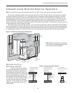
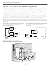
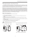
ENVISION RESIDENTIAL INSTALLATION MANUAL
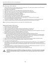
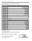
Setting Fan Speed - ECM
ECM2 fan motors have a 12-speed selector dip switch on the logic board (SW1) and are factory set for optimum perfor-
mance. To change speeds, select the appropriate speeds on dip switch SW1. Consult the ECM2 fan performance table
below for specifi c airfl ow and switch information.
CAUTION: Disconnect all power before performing this operation.
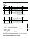
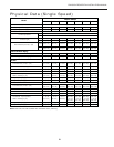
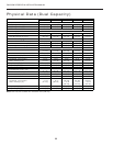
Fan Performance Data - ECM
ECM2
1
2
3
4
5
6
7
8
9
10
11
12
SW1
OnOff
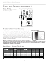
A 12-position DIP switch package on the control allows the airfl ow levels to be set for low, medium, and high
speed when using the ECM2 blower motor. Only three of the DIP switches can be in the "on" position.
The fi rst "on" switch (the lowest position number) determines the low speed fan setting.
The second "on" switch determines the medium speed fan setting.
The third "on" switch determines the high speed fan setting.
The example to the right shows SW1 on the control board confi gured for the following NS042 airfl ow settings.
Low Speed Fan: 900 CFM
Medium Speed Fan: 1150 CFM
High Speed Fan: 1450 CFM
•
•
•
•
•
•
Single Speed
Dual Capacity
MAX AIR FLOW DIP SWITCH SETTINGS
ESP123456789101112
400 500 600 700
800 900 1000 1100 1200
L M
H
400 500 600 700
800 900 1000 1100 1200
L M
H
650 750 850 1000 1100 1200
1300 1400 1500
L
MH
036
800 1000 1100 1300 1500 1600
1800
w/1hp*
L MH
650
800 900 1050 1150 1250 1350 1450 1550
L
MH
042
800
900 1000 1200 1400 1600 1700 1850 2000 2200 2300 2400
w/1hp* L M
H
650
800 900 1050 1150 1250 1350 1450 1550
L
MH
048
800
900 1000 1200 1400 1600 1700 1850 2000 2200 2300 2400
w/1hp*
L MH
800
950 1100 1300 1500 1750 1950 2100 2300
L
MH
800
950 1100 1300 1500 1750 1950 2100 2300
L
MH
5/30/06
Factory settings are at recommended L-M-H DIP switch locations CFM is controlled within ±5% up to the maximum ESP
M-H settings MUST be located within boldface CFM range Max ESP includes allowance for wet coil and standard filter
Lowest and Highest DIP switch settings are assumed to be L and H respectively
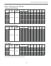
MAX AIR FLOW DIP SWITCH SETTINGS
ESP123456789101112
400 500 600 700
800 900 1000 1100 1200
L M
H
650 750 850 1000 1100 1200
1300 1400 1500
L
MH
038
800 1000 1100 1300 1500 1600
1800
w/1hp*
L MH
650
800 900 1050 1150 1250 1350 1450 1550
L
MH
049
800
900 1000 1200 1400 1600 1700 1850 2000 2200 2300 2400
w/1hp*
L
MH
800
950 1100 1300 1500 1750 1950 2100 2300
L M
H
800
950 1100 1300 1500 1750 1950 2100 2300
L
MH
5/30/06
Factory settings are at recommended L-M-H DIP switch locations CFM is controlled within ±5% up to the maximum ESP
M-H settings MUST be located within boldface CFM range Max ESP includes allowance for wet coil and standard filter
Lowest and Highest DIP switch settings are assumed to be L and H respectively
MODEL
022 0.50
026 0.50
0.75
030 0.50
036 0.50
0.75
042 0.50
0.75
048 0.50
MODEL
070 0.75
060 0.75
049 0.50
0.75
038 0.50
0.75
072 0.75
064 0.75