


38
ENVISION RESIDENTIAL INSTALLATION MANUAL
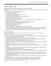
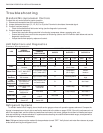
Troubleshooting
Standard Microprocessor Controls
To check the unit control board for proper operation:
1) Disconnect thermostat wires at the control board.
2) Jumper the desired test input (Y1, Y2, W, O or G) to the R terminal to simulate a thermostat signal.
3) If control functions properly:
• Check for thermostat and fi eld control wiring (use the diagnostic inputs mode).
4) If control responds improperly:
• Ensure that component being controlled is functioning (compressor, blower, reversing valve, etc.).
• Ensure that wiring from control to the component is functioning (refer to the LED Defi nition table below and use the
diagnostic outputs mode).
• If steps above check properly, replace unit control.
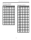
Refrigerant Systems
To maintain sealed circuit integrity, do not install service gauges unless unit operation appears abnormal. Compare the
change in temperature on the air side as well as the water side to the tables on pages 35-36. If the unit’s performance is not
within the ranges listed, and the airfl ow and water fl ow are known to be correct, gauges should then be installed and super-
heat and subcooling numbers calculated. If superheat and subcooling are outside recommended ranges, an adjustment to
the refrigerant charge may be necessary.
Note:
Refrigerant tests must be made with desuperheater turned “OFF”.
Verify that air and water fl ow rates are at proper
levels before servicing the refrigerant circuit.
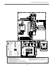
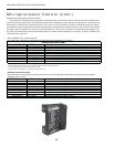
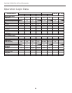
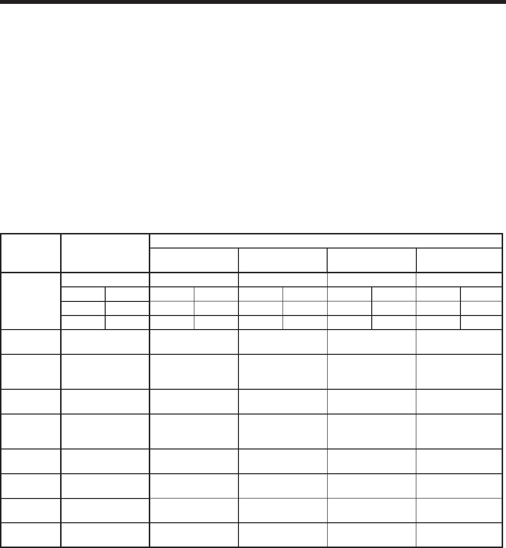
LED
NORMAL
DISPLAY MODE
DIAGNOSTIC MODES
CURRENT
FAULT STATUS
INPUTS OUTPUTS 1 OUTPUTS 2
Field Selection DIPS
SW2- 1 On SW2- 1 Off SW2- 1 NA SW2- 1 NA SW2- 1 NA
SW2- 6 On SW2- 6 On SW2- 6 Off SW2- 6 On SW2- 6 Off
SW2- 7 On SW2- 7 On SW2- 7 On SW2- 7 Off SW2- 7 Off
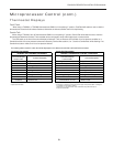
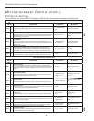
Drain
Drain Pan Overfl ow
Lockout
Drain Pan Overfl ow Y1
Compressor
(On or Low)
Blower
Low
Water Flow
FP Thermistor (Loop
<15º F, Well<30ºF)
Lockout
FP Thermistor (Loop
<15º F, Well<30ºF)
Y2
Compressor
(On or High)
Blower
Medium
High
Pressure
High Pressure >600
PSI Lockout
High Pressure >600 O Reversing Valve
Blower
High
Low
Pressure/
Compressor
Low Pressure <40
PSI Lockout or
Comfort Alert
Low Pressure <40
or Comfort Alert
G Fan Aux Heat 1
Airfl ow
ECM2 RPM <100
RPM
ECM2 RPM
<100 RPM
W DHW Pump Aux Heat 2
Status
Microprocessor
Malfunction
Not Used SL1 Loop Pump(s) Aux Heat 3
DHW Limit
HWL Thermistor
>130º
HWL Thermistor
>130°F
Not Used – Aux Heat 4
DHW Off
DHW Pump
Switch Off
DHW Pump
Switch Off
–––
LED Defi nitions and Diagnostics
Standard Microprocessor