


14
ENVISION RESIDENTIAL INSTALLATION MANUAL
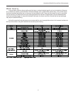
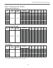
Auxiliary Heat Ratings
KW BTU/HR Min Envision Series Compatibility
Model 208V 230V Stages 208V 230V CFM 022 026 - 030 036 - 049 060 - 072
EAM(H)5 3.6 4.8 1 12,300 16,300 450
••
EAM(H)8 5.7 7.6 2 19,400 25,900 550
••
EAM(H)10 7.2 9.6 2 24,600 32,700 650
•
EAL(H)10 7.2 9.6 2 24,600 32,700 1100
••
EAL(H)15 10.8 14.4 3 36,900 49,100 1250
••
EAL(H)15-3 10.8 14.4 3 36,900 49,100 1250
••
EAL(H)20 14.4 19.2 4 49,200 65,500 1500
•
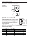
Electrical Connections (cont.)
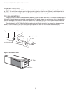
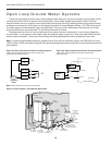
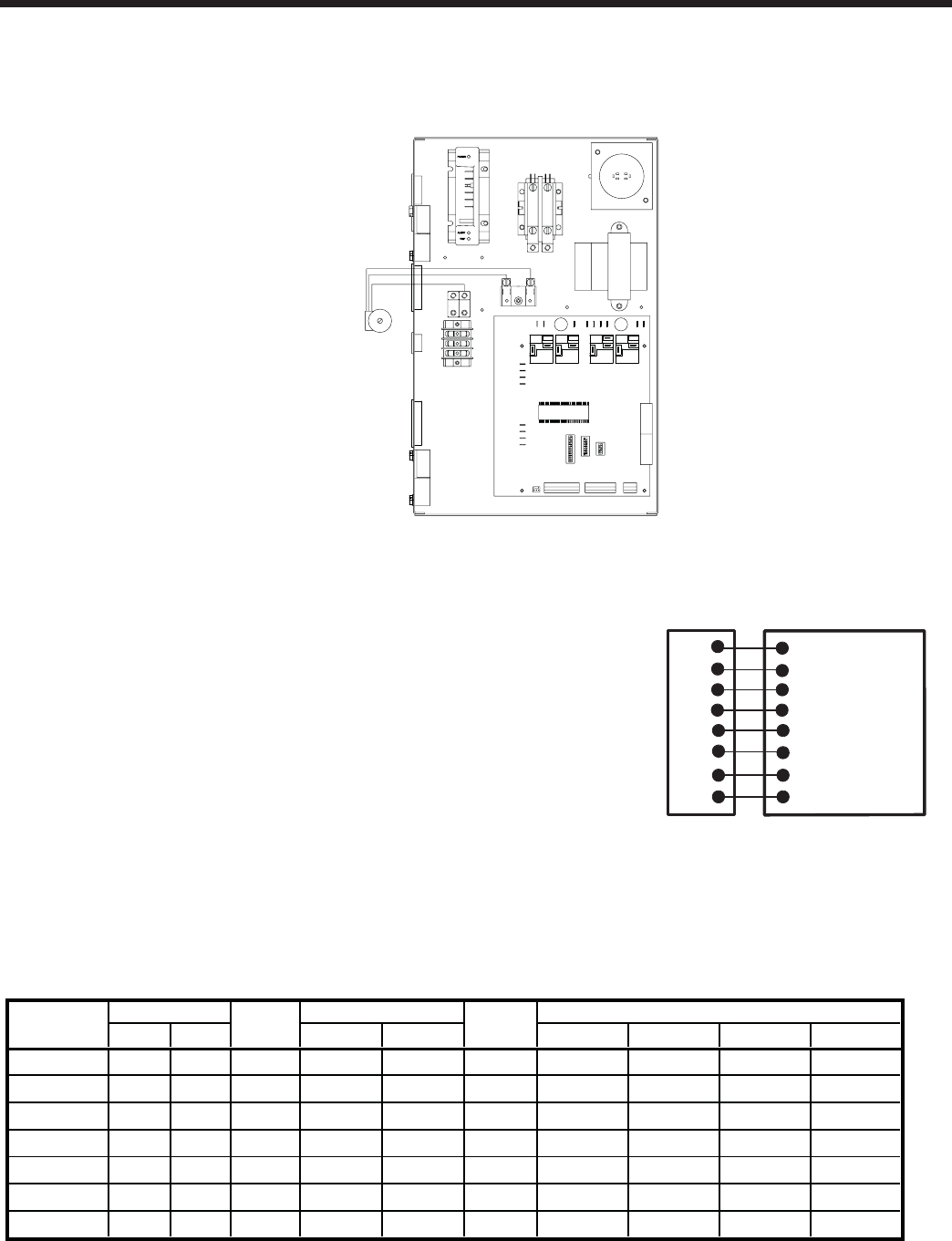
Pump Wiring
See Figure 14 for electrical connections
from control box to pumps.
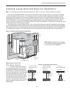
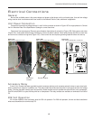
Electronic Thermostat
Position the thermostat subbase against the wall so that it is level and the
thermostat wires protrude through the middle of the subbase. Mark the position
of the subbase mounting holes and drill holes with a 3/16-inch bit. Install supplied
anchors and secure base to the wall. Thermostat wire must be 8-conductor, 18-
AWG wire. Strip the wires back 1/4-inch (longer strip lengths may cause shorts)
and insert the thermostat wires into the connector as shown. Tighten the screws
to insure secure connections. The thermostat has the same type connectors,
requiring the same wiring. See instructions enclosed in the thermostat for detailed
installation and operation information.
Note: DIP switch SW2-8 is required to be in the “OFF” position for the control to
operate with FaultFlash or ComforTalk thermostats. SW2-8 in the “ON” position confi gures the control to operate with typical
thermostats (continuous lockout signal). There must be a wire connecting Y2 on the microprocessor controller to 2nd stage
compressor on the thermostat for proper operation.
Figure 14: Pump Wiring 208-230/60/1
Figure 15: Thermostat Wiring
R
Y1
C
W
O
G
L
24VAC (Hot)
24VAC (Common)
Compressor (1st Stage)
Aux. Heat
Reversing Valve
Blower Relay
System Monitor
Microprocessor Controlle
r
Thermostat Connection
Y2
Compressor (2nd Stage)