


32
ENVISION RESIDENTIAL INSTALLATION MANUAL
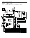
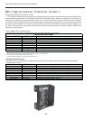
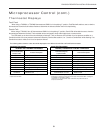
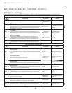
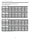
DIP Switch Settings
Prior to powering unit, ensure that all DIP switches on SW2 & SW3 are set properly according to the tables below.
FACTORY SETUP DIP SWITCHES (SW3)
DIP
SWITCH
NUMBER
DESCRIPTION OFF POSITION ON POSITION
SW 3- 1
Dual Capacity/Single-Speed
Confi gures the control for single-speed compressor operation or dual capacity opera-
tion.
Dual Capacity Opera-
tion
Single-Speed Operation
SW 3- 2
Zoned/Finish on Second Stage
This switch allows the unit to down stage with the thermostat when off and fi nish with
second stage when on. Finish on second stage reduces stage changing in recipro-
cating dual capacity compressors.
Normal - All Other
Systems
Finish on 2nd - Unzoned Dual
Capacity E Series or Premier
2 Speed
SW 3- 3
No RPM/RPM
Confi gures the control to monitor the RPM output of an ECM/ECM2 blower motor.
When using IntelliZone or a PSC fan motor, the control should be confi gured for “NO
RPM” sensing.
PSC Fan/RPM Moni-
toring Disabled
ECM-ECM2 Fan/RPM
Monitoring Enabled
SW 3- 4
Electric heat and ECM2
Allows backward compatibility with older Premier Series. In the Off position this
switch allows older electric heat board (17P501A01) and older ECM (square end)
compatibility. On is for all newer EH board (17P514A01) and ECM2 (round end).
Old EH & Old ECM Normal
SW 3- 5
On dual capacity units this switch allows stage change: on the fl y when off, and 1
minute delay when on. A delay is required on all reciprocating dual capacity units.
Envision E-Series or Premier
FIELD SELECTION DIP SWITCHES (SW2)
DIP
SWITCH
NUMBER
DESCRIPTION OFF POSITION ON POSITION
SW 2- 1
Service Test Mode
On the control, allows fi eld selection of “NORMAL” or “TEST” operational modes.
Test mode accelerates most timing functions 16 times to allow faster troubleshooting.
Test mode also allows viewing the “CURRENT” status of the fault inputs on the LED
display.
Test Mode Normal Speed Operation
SW 2- 2
Freeze Sensing Setting
Allows fi eld selection of freeze thermistor fault sensing temperatures for well water
(30°F) or antifreeze-protected (15°F) earth loops.
Loop Water Freeze
Protection 15° F
Well Water Freeze Protec-
tion 30° F
SW 2- 3
Accessory Relay
Allows fi eld selection of the accessory relay to operate with the compressor or fan.
Acc Relay Tracks Fan
Acc Relay Tracks Compres-
sor
SW 2- 4
Fan Speed Control
Allows fi eld selection of reduced fan speed (85% of selected medium and high speed
– ECM only) for cooling in the dehumidifi cation mode.
Dehumidifi cation Fan
Speeds
Normal Fan Speeds
SW 2- 5
Auxiliary Off
Disables 3rd-stage Heating. Full emergency heat would still be available if needed.
Disable Heating
Stage 3
Enable Heating
Stage 3
SW 2- 6
Diagnostics Inputs
Allows viewing the inputs from the thermostat to the control board such as Y1, Y2, O,
G, W, SL1-In on the LED display.
Diagnostic Inputs
Viewed at LEDs
Normal Display Viewed at
LEDs
SW 2- 7
Diagnostics Outputs
Allows viewing the outputs from the control board such as compressor, reversing
valve, blower, hot water pump, and loop pump on the LED display.
Diagnostic Outputs
Viewed at LEDs
Normal Display Viewed at
LEDs
SW 2- 8
Thermostat Selection
Confi gures the control for a pulsed lockout signal (ComforTalk and FaultFlash ther-
mostats) or continuous 5 VAC lockout signal.
Pulsed “L” signal Continuous “L” signal
Microprocessor Control (cont.)
NEW
]
NEW
]