


8
ENVISION RESIDENTIAL INSTALLATION MANUAL
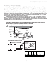
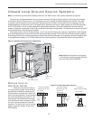
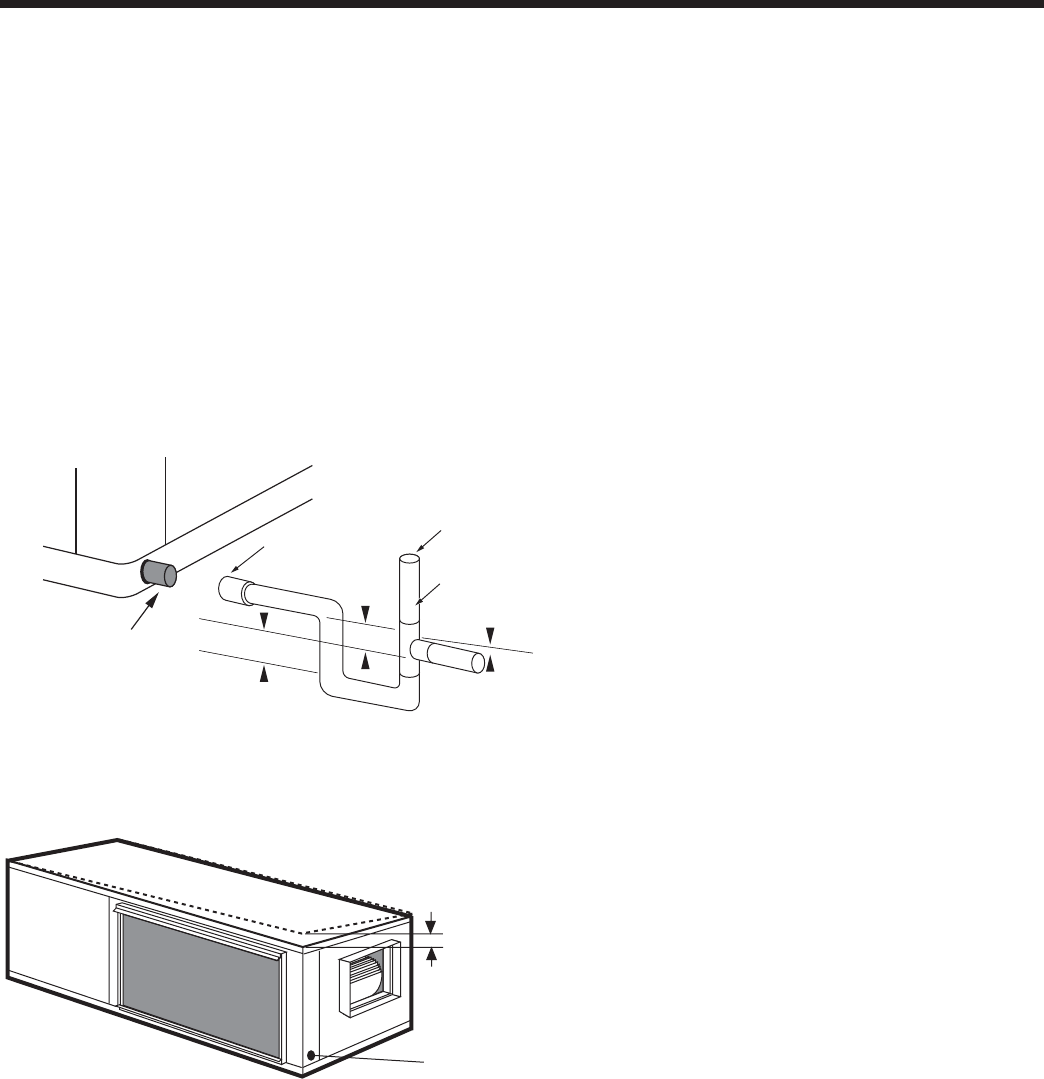
1/2'' Pitch
Drain
1.5"
1.5"
3/4” PVC tube stub
3/4" PVC
Coupling
Vent (if needed)
3/4" PVC
1/8" per foot
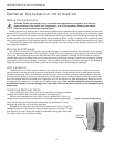
Figure 6: Unit Pitch for Drain
Figure 5: Horizontal Drain Connection
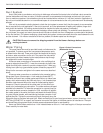
Freeze Protection
Set the freeze sensing switch SW2-2 on the printed circuit board for applications using a closed loop antifreeze solution
to “LOOP”. On applications using an open loop/ground water system (or closed loop no antifreeze), set this dip switch to
“WELL”, the factory default setting. (Refer to the Dip Switch Field Selection table on page 24.)
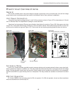
Condensate Drain
On vertical units, the internal condensate drain assembly consists of a drain tube which is connected to the drain pan, a
3/4-inch PVC female adapter and a fl exible connecting hose. The female adapter may exit either the front or the side of the
cabinet. The adapter should be glued to the fi eld-installed PVC condensate piping. On vertical upfl ow units, a condensate
hose is inside all cabinets as a trapping loop; therefore, an external trap is not necessary.
On horizontal units, a PVC stub is provided for condensate drain piping connection. An external trap is required (see
below). If a vent is necessary, an open stand pipe may be applied to a tee in the fi eld-installed condensate piping.