


13
ENVISION RESIDENTIAL INSTALLATION MANUAL
Electrical Connections
General
Be sure the available power is the same voltage and phase as that shown on the unit serial plate. Line and low voltage
wiring must be done in accordance with local codes or the National Electric Code, whichever is applicable.
Unit Power Connection
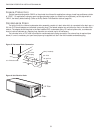
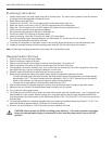
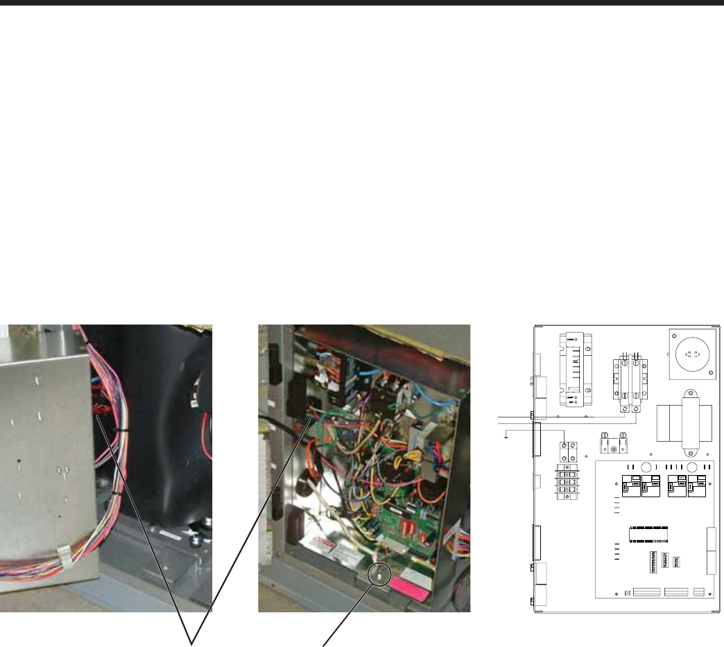
Connect the incoming line voltage wires to L1 and L2 of the contactor as shown in Figure 13C for single-phase unit. Consult
the Unit Electrical Data in the Specifi cation Catalog for correct fuse sizes.
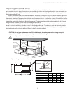
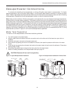
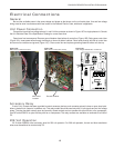
Open lower front access panel. Remove ground fastener from bottom of control box (Figure 13B). Swing open control box
(Figure 13A). Insert power wires through knockouts on lower left side of cabinet. Route wires through left side of control box
and connect to contactor and ground (Figure 13C). Close control box and replace grounding fastener before unit start-up.
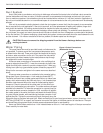
Accessory Relay
A set of “dry” contacts has been provided to control accessory devices, such as water solenoid valves on open loop instal-
lations, electronic air cleaners, humidifi ers, etc. This relay contact should be used only with 24 volt signals and not line voltage
power. The relay has both normally open and normally closed contacts and can operate with either the fan or the compressor.
Use DIP switch SW2-3 to cycle the relay with fan or compressor. The relay contacts are available on terminals #2 and #3 of
P3.
208 Volt Operation
All Envision 208/230 units are factory wired for 230 volt operation. For 208 volt operation, the red and blue transformer
wires must be switched on terminal strip PS.
Ground FastenerWire Insert
Location
Figure 13C:
Line Voltage 208-230/60/1 control box
L1
L2
Figure 13B:
Wire access (control box closed)
Figure 13A:
Wire access (control box open)