


29
ENVISION RESIDENTIAL INSTALLATION MANUAL
Microprocessor Control (cont.)
Heat, 3rd Stage (Y1,Y2,W) Dual Capacity Units
The hot water pump is de-energized which directs all heat
to satisfy the thermostat. The 1st stage of resistance heat is
energized 10 seconds after “W” input, and with continuous 3rd
stage demand, the additional stages of resistance heat engage
sequentially every 5 minutes.
Emergency Heat (W only)
The fan is started on high speed, and the fi rst stage of
resistance heat is energized 10 seconds after the "W" input.
Continuing demand will engage the additional stages of
resistance heat sequentially every 2 minutes.
Cooling Operation
In all cooling operations, the reversing valve directly
tracks the “O” input. Thus, anytime the “O” input is present,
the reversing valve will be energized.
Cool, 1st Stage (Y1,O)
The blower motor and hot water pump are started immediately,
the loop pump(s) is energized 5 seconds after the “Y1” input is
received. The compressor will be energized (on low capacity for
Dual Capacity units) 10 seconds after the “Y1” input. The ECM
blower will shift from low to medium speed 15 seconds after the
“Y1” input (85% of medium speed if in dehumidifi cation mode).
Cool, 2nd Stage (Y1, Y2, O) Single Speed Units
The fan changes to high speed (85% of high speed if in
dehumidifi cation mode) 15 seconds after the “Y2” input (ECM only).
Cool, 2nd Stage (Y1, Y2, O) Dual Capacity Units
The second stage compressor will be activated 5 seconds
after receiving a “Y2” input as long as the minimum fi rst stage
compressor run time of 1 minute has expired. The ECM blower
changes to high speed 15 seconds after the “Y2” input (85% of
high speed if in dehumidifi cation mode). The Comfort Alert will
delay the second stage compressor until 5 seconds after it
receives a “Y2” from the board.
Fan (G only)
The fan starts on low speed (PSC ON). Regardless of fan
input “G” from thermostat, the fan will remain on low speed for 30
seconds at the end of each heating, cooling or emergency heat
cycle.
A DIP switch on the Envision control allows fi eld selection of
15% reduced fan speeds for cooling in the dehumidifi cation mode
or medium and high fan speeds for cooling in the normal mode.
Note: Fan speed can change automatically only with an ECM Motor.
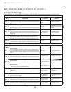
ECM2 Airfl ow Selection DIP Switches (SW1)
A 12-position DIP switch package on the Envision control
allows the airfl ow levels to be set for low, medium and high speed.
(Refer to the ECM Blower Table on page 15.)
Only three of the DIP switches can be in the “on” position.
The fi rst “on” switch (the lowest position number) determines the
“low speed fan” setting. The second “on” switch determines the
“medium speed fan” setting, and the third “on” switch determines
the “high speed fan” setting, (see page 15).
Lockout Conditions
During lockout mode, the appropriate unit and thermostat
lockout LEDs will illuminate. The compressor, loop pump, hot
water pump, and accessory outputs are de-energized. Unless the
lockout is caused by an ECM2 low RPM fault, the fan will continue
to run on low speed. If the thermostat calls for heating, emergency
heat operation will occur.
Comfort Alert lockouts cannot be reset at the thermostat.
All other lockout modes can be reset at the thermostat after
turning the unit off, then on, which restores normal operation but
keeps the unit lockout LED illuminated. Interruption of power to
the unit will reset a lockout without a waiting period and clear all
lockout LEDs.
High Pressure
This lockout mode occurs when the normally closed safety
switch is opened momentarily (set at 600 PSI).
Low Pressure
This lockout mode occurs when the normally closed low
pressure switch is opened for 30 continuous seconds (set at 40 PSI).
A low pressure fault may also be indicated when a Comfort Alert
lockout has occurred.
Freeze Sensing (Water Flow)
This lockout mode occurs when the freeze thermistor
temperature is at or below the selected freeze sensing point (well
30°F or loop 15°F) for 30 continuous seconds.
Condensate Overfl ow
This lockout mode occurs when the condensate overfl ow
level has been reached for 30 continuous seconds.
Fan RPM
The control board monitors fan RPM to sense operation.
This lockout mode occurs if the fan RPM falls below the low RPM
limit (100 RPM) for 30 continuous seconds (ICM only).