


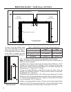


Secondary Installation
Pins
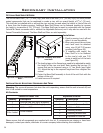
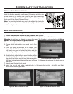
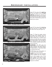
Figure 75. Third Stage Log Set Installation.
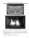
Figure 77. Fifth Stage Log Set Installation.
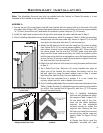
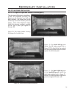
Figure 76. Fourth Stage Log Set Installation.
Figure 75: The center of the right log
ts onto the locator pin on the back
right log (see Figure 74). The front of
the log is to rest on the burner and the
back end of the log rests on the back
brick panel. Ensure the log does not
block any burn ports.
Figure 76: The center of the front log
ts onto the two (2) locator pins on
the valve cover tray (see Figure 75).
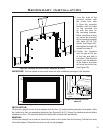
Figure 77: Place the ember chunks
and ember wool irregularly onto and
around the front of the burner to
create a realistic look. The ember wool
comes in chunks that can be ripped
into smaller pieces. The front log has
been removed for clarity. See Figure
78 for complete log and ember set-up
with the front log.
WARNINGS: DO NOT pack this
ember material as this could create an
unsafe condition. The pieces should
be lightly placed so they don’t block
any of the burner ports.
DO NOT allow any of the embers to
rest against the pilot assembly.
Caution: Use only the type of ember
material supplied with this replace.
Due to the irregular size of the
ember material, there may be more
than required. Use of other foreign
materials on the burners may create
dangerous conditions.
36