


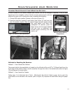
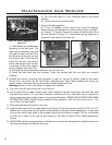
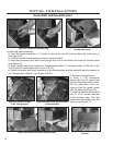
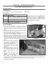

Figure 33: Spill Switch Wires Fed
Through Back Panel.
Initial Installation
QUALIFIED INSTALLERS ONLY
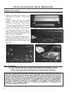
Figure 34: Remove Jumper
From Thermocouple.
Figure 35: Spill Switch Wires Connect
to Thermocouple.
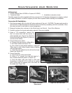
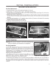
Figure 36: Remove Flue Slider Plate & Gasket.
Figure 37: Install Spill Switch on
Bracket.
f) Re-attach the back panel.
g) Using a T-20 screwdriver
remove the four (4) screws that
hold the ue slider bottom plate.
Pull the plate down then out,
ensuring that the gasket comes
with the plate (see Figure 36).
h) Install spill switch bracket with
two (2) of the screws removed
in the previous step. The spill
switch must be angled under the
opening (see Figure 37)
20
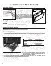
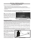
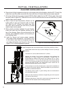
Figure 32: Install of Intake Air Plug.
2. Install spill switch assembly.
a) Use a at head screwdriver or ” socket to remove the nine (9) screws holding the back cover on
(see Figure 46).
b) Cut the tie strap from around the wires for the spill switch.
c) Feed the connector end of both wires through the hole in the bottom left corner of the back panel
(see Figure 33).
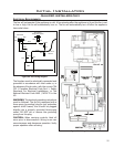
d) Using needle nose pliers remove the Thermocouple Cable #1 (connector closer to the rear of the
unit) from the Thermocouple (see Figure 34 & 45).
e) Attach the female spill switch connector to the thermocouple and the male spill switch connector to
the Thermocouple Cable #1 (see Figure 35 & 45).