


18
NOTES:
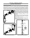
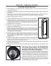
(1) The four (4) wood screws provided should be replaced with the appropriate fasteners for stucco,
brick, concrete, or other types of siding.
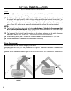
(2) For buildings with vinyl siding, a vinyl siding standoff, should be installed between the vent cap and
the exterior wall (see Figure 19). Attach the vinyl siding standoff to the horizontal termination. The
vinyl siding standoff prevents excessive heat from possibly melting the vinyl siding material. Note
that the horizontal vent termination bolts onto the at portion of the vinyl siding standoff (shaded
area in Figure 20), so that an air space will exist between the wall and the vent termination.
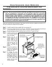
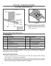
NOTES:
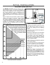
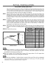
(1) The horizontal run of vent pipe must be level and should have a inch rise for every one foot
of run towards the termination. Never allow the vent to run downward. This could cause high
temperature and may present the possibility of a re.
(2) The location of the horizontal vent termination on the exterior wall must not be easily blocked or
obstructed. Refer to INITIAL INSTALLATION - VENT CONFIGURATIONS AND RESTRICTOR SETTINGS.
(3) When installing a vent pipe in a chase the minimum clearance to combustibles is 2” (51 mm).
(4) Maintain manufacturer’s clearances to combustibles with venting.
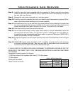
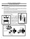
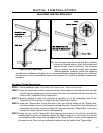
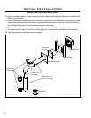
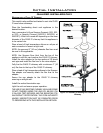
CORNER INSTALLATIONS:
Do not interfere with the structural integrity of the walls.
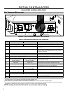
For installations with a 36” (915 mm) snorkel refer to Figure 21 and ‘Initial Installation - Installation of
Rear Vented’.
For other corner installations refer to Figure 22 and INITIAL INSTALLATION - VENT CONFIGURATIONS AND RESTRICTOR
SETTINGS.
2
1
/2”
(67mm)
InsideWall
OutsideWall
36”(915mm)
Snorkel
OutsideWall
OutsideWall
2
1
/2”
(67mm)
Figure 21: Corner installation rear vented with
snorkel.
Figure 22: Corner installation top vented.
Initial Installation
QUALIFIED INSTALLERS ONLY