


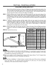
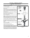

down to the roof level, as shown in Figure 24. Tighten the clamp around the pipe section. Use
a level to make sure the pipe is truly vertical. With roong nails, secure the support straps to
the roof. Seal the nails holes heads with non-hardening mastic. Trim the excess length of the
support straps that extend out beyond the edge of the ashing.
STEP 7. Slip the ashing over the pipe section protruding through the roof. Secure the base of the
ashing to the roof with roong nails. Use a non-hardening sealant between the uphill edge
of the ashing and the roof. Insure the roong material overlaps the top edge of the ashing
as shown in Figure 24. Verify that you have at least the minimum clearance to combustibles at
the roof line.
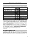
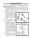
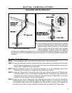
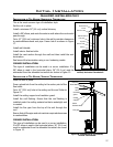
STEP 8. Continue to add pipe sections until the height of the vent cap meets the minimum code
requirements. Refer to Figure 25 and Table 4. Note that for steep roof pitches, the vent height
must be increased. In high wind conditions, nearby trees, adjoining roof lines, steep pitched
roofs, and other similar factors can result in poor draft, or down drafting. In these cases,
increasing the vent height may solve the problem.
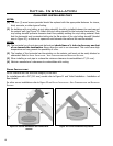
STEP 9. Slip the storm collar over the pipe, and push it down to the top of the roof ashing as shown
in Figure 24. Use the non-hardening sealant around the joint between the pipe and the storm
collar.
STEP 10. Twist-lock the vent cap.
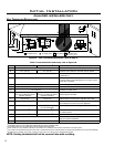
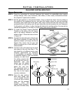
H
Dimension ‘H’ obtained
from table below.
Roof Pitch Minimum Height
Feet Meters
Flat to 7/8 1 0.3
Over 7/12 to 8/12 1.5 0.46
Over 8/12 to 9/12 2 0.61
Over 9/12 to 10/12 2.5 0.76
Over 10/12 to 11/12 3.25 0.99
Over 11/12 to 12/12 4 1.22
Over 12/12 to 14/12 5 1.52
Over 14/12 to 16/12 6 1.83
Over 16/12 to 18/12 7 2.13
Over 18/12 to 20/12 7.5 2.29
Over 20/12 to 21/12 8 2.44
Table 4: Minimum ‘H’ for Figure 25
Figure 25: Height of Vertical Termination;
Reference Table 4.
20
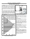
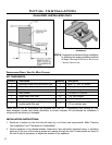
NOTES:
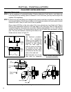
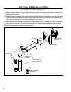
(1) If an offset is necessary in the attic to avoid obstructions, it is important to support the vent pipe
every 3 feet (91 cm), to avoid excessive stress on the elbows, and possible separation. Wall straps
are available for this purpose (see Figure 26).
(2) When ever possible, use 45° degree elbows instead of 90° degree elbows. The 45° degree elbow
offers less restriction to the ow of ue gases and intake air.
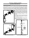
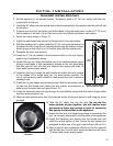
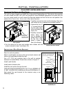
NOTES:
(1) For multi story installations. A ceiling restop is required at the second oor, and any subsequent
oors (see Figure 27). The opening should be framed to 10” (25.4 cm) x 10” (25.4 cm) inside
dimensions, in the same manner as shown in Figure 23.
Initial Installation
QUALIFIED INSTALLERS ONLY