


V
e
n
t
R
e
s
t
r
i
c
t
o
r
P
o
s
i
t
i
o
n
s
5
4
3
2
1
0’
(0m)
0’
(0m)
5’
(1.52m)
5’
(1.52m)
10’
(3.05m)
10’
(3.05m)
15’
(4.57m)
15’
(4.57m)
20’
(6.10m)
25’
(7.62m)
30’
(9.14m)
18’
(5.49m)
1
2
3
4
5
1
2
3
4
5
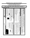
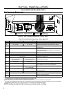
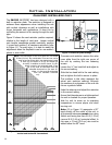
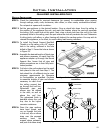
Figure 11: Restrictor plate settings.
Initial Installation
QUALIFIED INSTALLERS ONLY
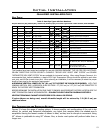
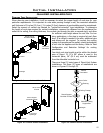
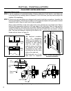
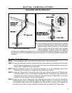
Figure 12. Possible Vent Congurations for Top Vented;
Vertical and Horizontal Terminations.
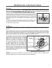
The ENVIRO WESTPORT has been designed with a
built in restrictor plate. The restrictor is designed to
enhance ame appearance when installing this unit
with vertical chimneys as well as installations with
longer horizontal vent applications. It does this by
controlling the amount of air moving through the vent
pipe.
Figure 12 shows the vent restrictor position required,
relative to the length of vent pipe. Longer vertical
vent lengths necessitate greater restriction; position
1 is open and position 5 is maximum restriction (refer
to Figure 11). To avoid injury, it is best to make this
adjustment when the replace is cool or use welder’s
gloves or oven mitts.
NOTE: The total length of the vent pipes can not exceed
30 feet (9.14 m). Any combination of rise and run can be
used as long as it lays within the shaded area (a total
of three (3) 90° elbows or six (6) 45° elbows can
be used). In addition to what is shown, if a 90°
elbow is used in the horizontal plane, 3 feet
(91.4 cm) must be subtracted from the
allowable horizontal run (for each 45°
elbow, 1 feet must be subtracted
from the allowable horizontal
run).
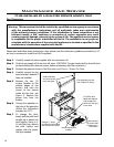
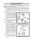
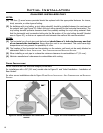
To access vent restrictor remove the valve
cover plate from the right rear corner of
the unit by undoing the two fastening
screws.
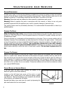
Loosen the ” hex head bolt and adjust to
the correct setting.
Slide the hex head bolt to the next setting
and re-tighten the bolt to secure in place.
The numbers in this chart represent the
actual vent restrictor settings. Although
the numbers do not appear on the unit use
this as a guide to follow.
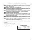
Undo the setscrew and adjust the restrictor
to the correct setting.
Ensure that the setscrew is re tightened and
the unit is checked for proper operation.
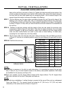
Wait for unit to warm up to operating
temperature to ensure proper and clean
burning unit.
Note: 0,0 in Figure 12 represents a 90˚
bend directly off the outlet of the unit, in
all horizontal instances except when using
Selkirk and having less than a 4 ft (1.22 m)
rise and 8 ft (2.44 m) horizontal offset. In
this case, a 1 foot (30.5 cm) rise must be
added below the 90˚ bend.
14