


System Operation, Testing and Maintenance
Liebert
®
Mini-Mate2
™
58
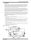
Hot Gas Bypass
Operation
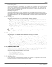
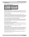
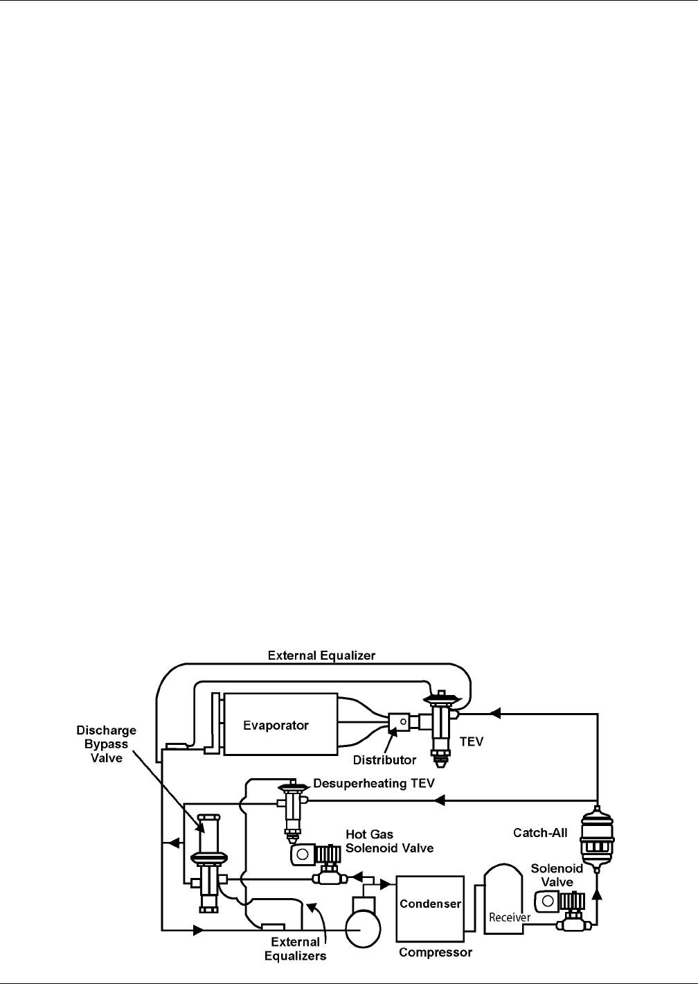
The hot gas bypass valve is installed between the compressor discharge piping and suction piping,
bypassing the condenser and evaporator coils. The discharge gas mixes with the suction gas, raising
the suction temperature and pressure and decreasing the mass flow through the evaporator. The
higher suction temperatures could cause compressor overheating, therefore a separate liquid
quenching valve is provided to mix refrigerant from the system liquid line with the discharge gas
before mixing with the suction gas entering the compressor.
During normal operation, when the evaporator is under full load the hot gas bypass equalizer
pressure will remain high enough to keep the valve port closed. If the evaporator load decreases, the
evaporator temperature and pressure will drop. When the suction pressure reduces below the hot gas
bypass valve setting the hot gas bypass valve opens diverting some of the refrigerant flow back to the
compressor suction. The liquid quenching valve bulb senses this increased superheat and opens,
allowing liquid refrigerant to mix with the discharge gas, desuperheating it.
Proper mixing of the three refrigerant paths ensures stable operation and system performance. The
liquid quenching valve bulb must be located downsteam of all these connections to control superheat
at the compressor inlet. Superheat settings for the liquid quenching valve are chosen to maintain
consistency with the system expansion valve. During hot gas bypass operation higher superheats, 50-
60°F (19 to 15°C), may be observed at the compressor. The liquid quenching valve is internally
equalized and superheat is not adjustable.
Adjustment
1. Install the suction and discharge pressure gauge.
2. Adjust temperature setpoint to call for cooling so that the refrigeration compressor will run
continuously.
3. Remove the TOP adjusting nut from the valve.
4. Insert an Allen wrench in the brass hole at top of valve in adjusting port and turn CLOCKWISE if
a higher evaporator temperature is required. Adjust no more than 1/4 turn at a time. Let the
system stabilize for 15 minutes before determining if additional adjustment is necessary.
5. After obtaining the suction pressure required, reinstall cap tightly making sure there are no
leaks.
6. Let the evaporator operate for approximately 10 to 15 minutes to make sure the suction pressure
is within the range desired.
7. There may be a fluctuation of approximately 3 to 6 PSIG (21 to 41 kPa) on the evaporator due to
the differential on the hot gas bypass.
8. Return temperature setpoint to the desired setting.
Figure 30 Hot gas bypass