


Site Preparation and Installation
Liebert
®
Mini-Mate2
™
24
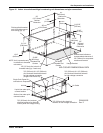
Power Connections
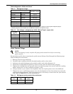
All power and control wiring and ground connections must be in accordance with the National
Electrical Code (NEC) and local codes. Refer to Unit serial tag data for electrical requirements.
Voltage supplied must agree with the voltage specified on the unit serial tag. If a field supplied
disconnect switch is required, it may be bolted to the ceiling unit, but not to any of the removable
panels. This would interfere with access to the unit. Make sure that no refrigerant lines are
punctured when mounting the disconnect switch.
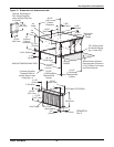
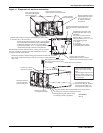
Route the electrical service conduit through the hole provided in the cabinet and terminate it at the
electric box. Make connections at the factory terminal block or disconnect switch, L1, L2, L3. Connect
earth ground to lug provided. See transformer label for primary tap connections. Installer will need to
change transformer primary taps if applied unit voltage is other than pre-wired tap voltage.
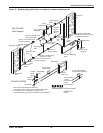
An optional single point power kit is available for units that are close coupled (See 5.4.3 - Piping
Connections and Coolant Requirements). This kit should be mounted inside the condensing unit
before installing the unit in the ceiling. Specific installation instructions are included with the single
point power kit.
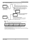
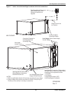
Control Connections
A field-supplied, 4-wire control connection (24 VAC) is required between the evaporator and the
condensing unit. Control wiring must be installed in accordance with the National Electrical Code
(NEC) Class 2 circuit. Glycol cooled units also require a two-wire control connection to the drycooler
and pump. A Class 1 circuit is required for Water/Glycol units.
Control wiring between the evaporator and the condensing unit must not allow a voltage drop in the
line of more than 1 volt (16 gauge minimum for 75 feet). Do not connect additional electrical devices to
the control circuit. The circuit breaker, contained in the transformer housing, is sized only for the
factory-supplied control system.
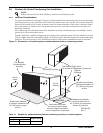
Additional control wiring will be required if your system includes other optional monitoring and
control devices.
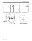
Four (4) wire (thermostat type) must be connected between the evaporator control board and the wall
box. See Figure 14.
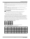
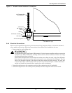
!
WARNING
Risk of loose electrical wiring connections. Can cause overheating of wire, smoke and fire
resulting in building and equipment damage, serious injury or death.
Use copper wiring only. Verify periodically that all connections are tight.