


Site Preparation and Installation
17 Liebert
®
Mini-Mate2
™
5.3 Equipment Inspection Upon Receipt
When the unit arrives, do not uncrate equipment until it is close to its final location. All required
assemblies are banded and shipped in corrugated containers. If you discover any damage when you
uncrate the unit, report it to the shipper immediately. If you later find any concealed damage, report
it to the shipper and to your Liebert supplier.
5.4 Installing the Ceiling Units
The evaporator unit and indoor condensing unit are usually mounted above the ceiling and must be
securely mounted to the roof structure. The ceiling and ceiling supports of existing buildings may
require reinforcements. Be sure to follow all applicable national and local building codes. Use
field-supplied threaded suspension rods and 3/8"–16 factory hardware kit.
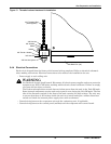
Recommended clearance between ceiling grids and building structural members is unit height plus
three inches (76.2mm).
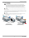
Install the four field-supplied rods by suspending them from suitable building structural members.
Locate the rods so that they will align with the four mounting holes in the flanges that are part of the
unit base.
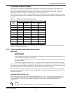
Using a suitable lifting device that is rated for the weight of the unit (see 5.2 - Ceiling Unit
Weights), raise the unit up and pass the threaded rods through the four mounting holes in the
flanges that are part of the unit base.
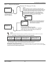
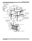
Attach the threaded rods to the unit flanges using the supplied nuts and grommets (see Figure 13).
The rubber grommets provide vibration isolation.
1. Use the plain nuts to hold unit in place. Adjust these nuts so that the weight of the unit is
supported evenly by the four rods, does not rest on the ceiling grid and is level.
2. Use the Nylock nuts to “jam” the plain nuts.
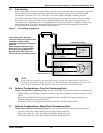
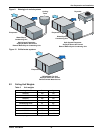
5.4.1 Close Coupled Installations
If the evaporator and condensing units are to be mounted side-to-side (close coupled), hang each unit
before connecting them together (see Figure 15). Align bolt holes in the condensing unit and in the
evaporator. Insert rubber spacers and secure four (4) sets of hardware provided. Align the refrigerant
connections and tighten them as described in 5.4.3 - Piping Connections and Coolant
Requirements.
5.4.2 Evaporator Air Distribution
Filter Box
The optional filter box mounts directly to the return air opening of the evaporator. The filter box is
supplied with 1" (25.4mm) duct flange connection, quantity two, 20" x 20" x 4" nominal
(508mm x 508mm x 102mm) filters and a 1" (25.4 mm) duct flange for use on the supply air opening.
Filters are MERV 8 efficiency per ASHRAE Standard 52.2-2007.
!
WARNING
Risk of ceiling collapse and heavy unit falling. Can cause building damage, serious injury or
death.
Verify that the supporting roof structure is capable of supporting the weight of the unit(s) and
the accessories during installation and service. (See 5.2 - Ceiling Unit Weights.)
Securely anchor the top ends of the suspension rods and verify that all nuts are tight.
NOTE
The units must be level in order to drain condensate properly.
NOTE
Do not operate the unit without filters installed in return air system.