


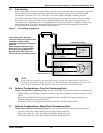
Figure 10 Chilled water systems. . . . . . . . . . . . . . . . . . . . . . . . . . . . . . . . . . . . . . . . . . . . . . . . . . . . . . . . . . . . 16
Figure 11 Refrigerant piping diagram . . . . . . . . . . . . . . . . . . . . . . . . . . . . . . . . . . . . . . . . . . . . . . . . . . . . . . . 20
Figure 12 Evaporator unit dimensional data . . . . . . . . . . . . . . . . . . . . . . . . . . . . . . . . . . . . . . . . . . . . . . . . . . 22
Figure 13 Threaded rod and hardware kit installation . . . . . . . . . . . . . . . . . . . . . . . . . . . . . . . . . . . . . . . . . . 23
Figure 14 Evaporator unit electrical connections . . . . . . . . . . . . . . . . . . . . . . . . . . . . . . . . . . . . . . . . . . . . . . 25
Figure 15 Close coupled installation. . . . . . . . . . . . . . . . . . . . . . . . . . . . . . . . . . . . . . . . . . . . . . . . . . . . . . . . . 26
Figure 16 Indoor air-cooled centrifugal condensing unit dimensions and pipe connections . . . . . . . . . . . . . 28
Figure 17 Indoor air-cooled centrifugal condenser electrical connections . . . . . . . . . . . . . . . . . . . . . . . . . . . 29
Figure 18 System piping with indoor or outdoor air-cooled condensing unit . . . . . . . . . . . . . . . . . . . . . . . . . 30
Figure 19 Dimensions—Air-cooled systems, standard ambient outdoor condensing module . . . . . . . . . . . . 31
Figure 20 Dimensions—Air-cooled systems, high ambient and Quiet-Line condensing module . . . . . . . . . 32
Figure 21 Indoor water/glycol condensing unit dimensional data . . . . . . . . . . . . . . . . . . . . . . . . . . . . . . . . . 34
Figure 22 Indoor water/glycol condensing unit electrical field connections . . . . . . . . . . . . . . . . . . . . . . . . . . 35
Figure 23 System piping with indoor water/glycol cooled condensing unit . . . . . . . . . . . . . . . . . . . . . . . . . . 36
Figure 24 Optional free-cooling coil (3-way valve) on water/glycol units . . . . . . . . . . . . . . . . . . . . . . . . . . . . 37
Figure 25 Optional hot water reheat (two-way valve) . . . . . . . . . . . . . . . . . . . . . . . . . . . . . . . . . . . . . . . . . . . 37
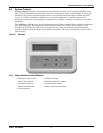
Figure 26 Wall box . . . . . . . . . . . . . . . . . . . . . . . . . . . . . . . . . . . . . . . . . . . . . . . . . . . . . . . . . . . . . . . . . . . . . . . 39
Figure 27 Control menu. . . . . . . . . . . . . . . . . . . . . . . . . . . . . . . . . . . . . . . . . . . . . . . . . . . . . . . . . . . . . . . . . . . 48
Figure 28 Control board—inside evaporator . . . . . . . . . . . . . . . . . . . . . . . . . . . . . . . . . . . . . . . . . . . . . . . . . . 49
Figure 29 Wall box board. . . . . . . . . . . . . . . . . . . . . . . . . . . . . . . . . . . . . . . . . . . . . . . . . . . . . . . . . . . . . . . . . . 49
Figure 30 Hot gas bypass. . . . . . . . . . . . . . . . . . . . . . . . . . . . . . . . . . . . . . . . . . . . . . . . . . . . . . . . . . . . . . . . . . 58
TABLES
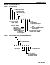
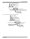
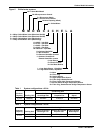
Table 1 System configurations—60 Hz . . . . . . . . . . . . . . . . . . . . . . . . . . . . . . . . . . . . . . . . . . . . . . . . . . . . . . 5
Table 2 System configurations—50 Hz . . . . . . . . . . . . . . . . . . . . . . . . . . . . . . . . . . . . . . . . . . . . . . . . . . . . . . 5
Table 3 Application limits, evaporator and chilled water units*. . . . . . . . . . . . . . . . . . . . . . . . . . . . . . . . . 14
Table 4 Application limits, indoor and outdoor air-cooled condensing units . . . . . . . . . . . . . . . . . . . . . . . 14
Table 5 Application limits, indoor water/glycol cooled condensing units . . . . . . . . . . . . . . . . . . . . . . . . . . 14
Table 6 Unit weights . . . . . . . . . . . . . . . . . . . . . . . . . . . . . . . . . . . . . . . . . . . . . . . . . . . . . . . . . . . . . . . . . . . 16
Table 7 Evaporator external static pressure . . . . . . . . . . . . . . . . . . . . . . . . . . . . . . . . . . . . . . . . . . . . . . . . 18
Table 8 Recommended refrigerant line sizes . . . . . . . . . . . . . . . . . . . . . . . . . . . . . . . . . . . . . . . . . . . . . . . . 19
Table 9 Equivalent lengths for various pipe fittings, ft (m). . . . . . . . . . . . . . . . . . . . . . . . . . . . . . . . . . . . . 19
Table 10 Pipe length and condenser elevation relative to evaporator . . . . . . . . . . . . . . . . . . . . . . . . . . . . . 20
Table 11 Refrigerant charge . . . . . . . . . . . . . . . . . . . . . . . . . . . . . . . . . . . . . . . . . . . . . . . . . . . . . . . . . . . . . . 21
Table 12 Line charges - refrigerant per 100 ft. (30m) of Type L copper tube . . . . . . . . . . . . . . . . . . . . . . . . 21
Table 13 Refrigerant quick connect sizes and torque. . . . . . . . . . . . . . . . . . . . . . . . . . . . . . . . . . . . . . . . . . . 21
Table 14 Weights for standard ambient outdoor condensing modules, air-cooled systems . . . . . . . . . . . . . 31
Table 15 Net weight, high ambient and Quiet-Line condensing modules, air-cooled systems . . . . . . . . . . 32
Table 16 Night and weekend setback plan . . . . . . . . . . . . . . . . . . . . . . . . . . . . . . . . . . . . . . . . . . . . . . . . . . . 41
Table 17 Default setpoints and allowable ranges. . . . . . . . . . . . . . . . . . . . . . . . . . . . . . . . . . . . . . . . . . . . . . 41
Table 18 Setup functions, default values and allowable ranges . . . . . . . . . . . . . . . . . . . . . . . . . . . . . . . . . . 43
Table 19 Alarm default time delays . . . . . . . . . . . . . . . . . . . . . . . . . . . . . . . . . . . . . . . . . . . . . . . . . . . . . . . . 44
Table 20 Equipment switch settings (unit control board) . . . . . . . . . . . . . . . . . . . . . . . . . . . . . . . . . . . . . . . 46
Table 21 Switch settings (wall box board) . . . . . . . . . . . . . . . . . . . . . . . . . . . . . . . . . . . . . . . . . . . . . . . . . . . 46
Table 22 Cooling and dehumidification load response of hot gas bypass . . . . . . . . . . . . . . . . . . . . . . . . . . . 50
Table 23 Typical discharge pressure . . . . . . . . . . . . . . . . . . . . . . . . . . . . . . . . . . . . . . . . . . . . . . . . . . . . . . . . 57
Table 24 Humidifier control board DIP switch settings. . . . . . . . . . . . . . . . . . . . . . . . . . . . . . . . . . . . . . . . . 62
Table 25 Troubleshooting. . . . . . . . . . . . . . . . . . . . . . . . . . . . . . . . . . . . . . . . . . . . . . . . . . . . . . . . . . . . . . . . . 64