


44
42
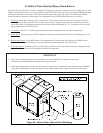
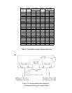
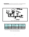
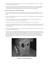
B. TANKLESS HEATER PIPING
If the Series 32 water boiler is installed with an optional tankless heater, pipe the heater as shown in Figure 32. The
components in this system and their functions are as follows:
1) Mixing Valve (Required) - During the heating season, the water exiting the tankless heater may be 180 degrees or
more. The mixing valve blends hot water leaving the tankless heater with cold water so as to maintain the hot water
supplied to the fixtures at a fixed temperature. This saves energy, increases the amount of usable hot water available
to the homeowner, and reduces the risk of scalding.
Install a mixing valve with a setting range of approximately 110 to 130F. Follow the manufacturer’s instructions for
installing this valve. Usually a “heat trap” will be required between the coil and the “hot” connection on the mixing
valve.
2)
Flow Restrictor (Recommended) - If water is drawn from the tankless coil at a rate in excess of the rating in Table 9,
the temperature of the hot water may be too low to be of use. The use of a flow restrictor will prevent this problem by
limiting the rate at which water can pass through the tankless heater. If a restrictor is used, select one having a rating
inGPM approximately equal to the rating shown in Table 9. If possible, locate this restrictor at least 3 feet from the
tankless heater inlet so that it is not subjected to excessive temperatures when no water is flowing through the coil.
3) Pressure Relief Valve (Required) - Limits the pressure in the tankless heater and piping. Use an ASME constructed
valve designed for domestic water service, such as the Watts #3L. Note that this is a pressure relief valve, not a T&P
valve. Select a valve with a pressure setting less than or equal to the working pressure marked on the tankless coil.
Pipe the discharge to a safe location using piping the same size as the discharge connection on the valve.
4) Hose Bib Valves (Recommended) - These valves permit the coil to be periodically “backflushed” to remove sediment.
5) Globe or Ball Valve (Recommended) - Used to adjust the flow through the entire tankless heater system if needed.
6) Unions (Required) - Tankless heaters may require periodic gasket replacement or other maintenance which requires
removal of the heater from the boiler. Install unions anywhere in the tankless heater piping that will facilitate removal
of the heater.
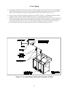
7) Backflow Preventer (Required in Massachusetts) - If required by local codes, install a backflow preventer in the cold
water connection to the tankless coil just upstream of the piping shown in Figure 32. Install in accordance with local
codes and the backflow preventer’s installation instructions. Also install a potable water expansion tank on the outlet
side of the backflow preventer (between the backflow preventer and the piping shown in Figure 32).
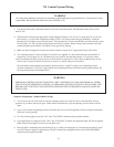
WARNING
A mixing valve does not eliminate the risk of scalding.
• Set the mixing valve and boiler low limit adjustments as low as possible.
• Feel water before showering or bathing
• If anti-scald or anti-chill protection is required, use devices specifically designed for such service. Install and
maintain these devices in accordance with the manufacturer’s instructions. Do not use the mixing valve as a
substitute for pressure balancing valves or other devices required by plumbing codes to protect against
scalding.