


39
37
CAUTION
• INSTALL BOILER SO THAT THE GAS IGNITION SYSTEM COMPONENTS ARE PROTECTED FROM
WATER (DRIPPING, SPRAYING, RAIN, ETC.) DURING APPLIANCE OPERATION AND SERVICE
(CIRCULATOR REPLACEMENT, ETC.).
• OPERATION OF THIS BOILER WITH CONTINUOUS RETURN TEMPERATURES BELOW 120°F CAN
CAUSE SEVERE HEAT EXCHANGER CORROSION DAMAGE.
• OPERATION OF THIS BOILER IN A SYSTEM HAVING SIGNIFICANT AMOUNTS OF DISSOLVED
OXYGEN CAN CAUSE SEVERE HEAT EXCHANGER CORROSION DAMAGE.
• DO NOT USE TOXIC ADDITIVES, SUCH AS AUTOMOTIVE ANTIFREEZE, IN A HYDRONIC SYSTEM.
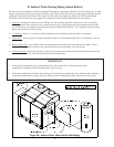
IX Water Boiler Piping
A. Heating System Piping
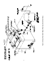
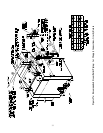
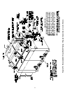
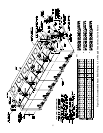
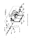
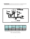
1) Figure 30 shows the recommended water boiler system piping. Use Table 8 to determine the supply riser, supply
header, return header and boiler return piping connection sizes for the appropriate boiler model. On boilers
requiring one supply riser, use the supply connection opposite the return connection. Install the trim on the same
end as the supply connection. Additional information on hydronic system design may be found in the I=B=R
Advanced Installation and Piping Guide (Pub. #250) published by the Hydronics Institute in Berkeley Heights,
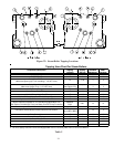
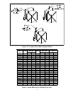
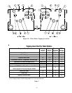
NJ or the ASHRAE Systems Handbook. Table 7 shows the use of all boiler tappings on water boilers. The
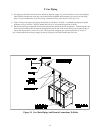
tapping letter designations referenced are shown in Figure 29. The water trim components are as follows:
a. Pressure Gauge – Install in tapping “D”. Tapping “D” must be reduced from ½” to ¼”. DO NOT TIGHTEN
THE GAUGE BY ITS CASE.
b. Low Water Cut-off – (Required in some situations) - A low water cutoff is required when the boiler is installed
above radiation. In addition, some codes, such as ASME CSD-1, require low water cutoffs. Codes may also
require that this low water cutoff have a manual reset function. When a probe low water cut-off is used, install it
in the supply piping above the boiler with no intervening valves between it and the boiler.
c. Limit Controls – All Series 32 water boilers are supplied with an L4006A operating temperature limit control.
In addition, a L4006E manual reset control is supplied on boilers with the CSD-1 control package. Install the
immersion well supplied with the L4006A in Tapping “C” with a bushing. Insert the bulb of the control in the
well until it rests against the bottom of the well. Bend the tubing if necessary to provide enough force to hold
the bulb against the bottom of the well. Avoid making a sharp bend in the tubing as this can cause the control to
malfunction. Tighten the screw on the bottom of the control so that it is securely clamped onto the well. When
an L4006E is used, install it in the supply riser on the same side of the boiler as the L4006A. Install it in a well
in the same manner as the L4006A.
d.Pressure Relief Valve (Required) - Before installing the relief valve, examine the tag on the valve and confirm
that it has a capacity greater than or equal to the boiler’s gross output. Also confirm that its pressure setting is
less than or equal to that marked on the boiler sections for water. Install Relief Valves in the “C” tapping on the
opposite end of the boiler from the other trim. Install the relief valve using the elbow and nipples provided so
that its’ spindle is vertically oriented (Figure 30).
Pipe the discharge of the relief valve to a location where hot water and steam will not create a hazard or cause
property damage if the valve opens. The discharge pipe must be the same size as the outlet connection on the
safety valve and must terminate in unthreaded pipe. The relief valve discharge piping must be in an area where it
is not likely to become plugged by debris or subjected to freezing.