


25
23
VII Venting
Vent installation must be in accordance with local building codes, or the authority having jurisdiction, or the
National Fuel Gas Code, NFPA 54/ANSI Z223.1.
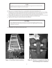
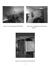
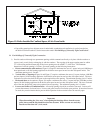
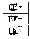
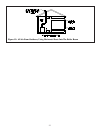
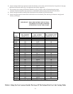
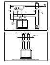
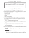
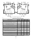
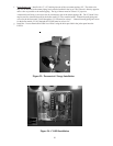
Typical vent installations are shown in Figures 20 and 21. The vent system shown in Figure 20 uses a common vent
for all boiler modules. In Figure 21, each boiler module is equipped with its own vent. The vent system in Figure 21 is
ideal on large boilers with many individually controlled base modules as the vent system will not be effectively
oversized when only a single module is firing.
1) Acceptable Chimneys - The following chimneys may be used to vent Series 32 boilers:
• Listed Type B or L gas vent - Install in accordance with the manufacturer’s instructions, the terms of its listing, and
applicable codes.
• Masonry Chimney - The masonry chimney must be constructed in accordance with the Standard for Chimneys,
Fireplaces, Vents, and Solid Fuel Burning Appliances (NFPA 211) and lined with a clay liner or other listed lining
system. Do not vent a Series 32 boiler into an unlined chimney.
2) Acceptable Vent Connectors - The following may be used for vent connectors:
• Listed type B or L Gas Vent
• Single Wall Galvanized Pipe - Use 0.018” (26 gauge or heavier). The size and location of the chimney may not
permit the use of a single wall connector in some cases. See the National Fuel Gas Code. Do not use single wall
pipe for vent connectors in attics.
• Other Vent Connectors Permitted by the National Fuel Gas Code.
3) Chimney and Vent Connector sizing – If the entire vent system (chimney and vent connector) are constructed from
Type “B” vent, size the vent system using the National Fuel Gas Code. Where possible, also use the National Fuel
Gas Code to size vents employing single wall connectors and/or masonry chimneys. The minimum chimney size of
the 32-475 is 12”, even if the National Fuel Gas Code permits a smaller size. For boilers with more than one module,
use the Multiple Appliance vent section of the code and treat each base module as though it were a separate boiler.
For boilers with more than one module, the vent connector is always the same size as the module’s flue collar.
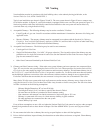
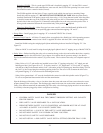
Many Series 32 boiler vent systems with single wall connectors and/or masonry chimneys are too large to be sized
using the National Fuel Gas Code. In these cases Table 4 may be used to size the vent system. The vent sizes shown
in Table 4 are based on the following assumptions:
· Chimney Height (Dimension “H”) at least 20 ft high
· Total length of lateral (“Lm”) less than or equal to that shown in Table 4
· No more than one 90 elbow is permitted in lateral common venting
· Vent connectors and common vent lateral constructed of single wall pipe or “B” vent
· Chimney is constructed of B vent or is a lined masonry chimney in good condition
· No other appliances are connected into the vent system
· Listed Chimney Cap is used
If any of these assumptions are not valid, and where the National Fuel Gas Code cannot be used, use other accepted
chimney design methods such as those shown in Chapter 30 of the ASHRAE HVAC Systems and Equipment Hand-
book.
4) Do not connect the boiler into a chimney flue serving an open fireplace or other solid fuel appliance.
5) Prior to boiler installation, inspect chimney for obstructions or other defects and correct as required. Clean chimney
as necessary.