


12
V Knockdown Boiler Assembly Instructions
10
A. Prior To Assembly
1) Thoroughly inspect the cast iron heat exchanger sections for any shipping damage, i.e. cracks in the castings, broken lugs
or punctures due to mishandling.
2) Do not use a damaged heat exchanger section. Replace it with an undamaged heat exchanger section.
3) Keep the base in the shipping carton until it is time to perform the assembly. This keeps foreign material from contami-
nating the burners or creating other hazards. Do not use the base assembly if there are any signs of visible damage.
4) Review all of the installation requirements in this installation manual.
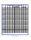
5) Verify that all needed components are on hand. A complete list of all sections and cartons that should be on hand,
along with their contents, can be found in the Parts Section. A summary of the cartons and their contents is shown
below. All boilers except the 32-475 use multiple base modules and therefore require multiple Base Cartons and
Intermediate Cartons. All boilers larger than the 32-855 require multiple Section Joiner Cartons. Some parts, such as
jacket screws and jacket mounting brackets are packed in both the Base Carton and the Base Side Panel Carton.
B. Base Assembly
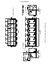
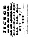
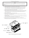
1) Each base module is tested and shipped assembled.
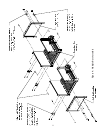
a. All boilers are assembled using base modules with inputs of 285, 380 and 475 MBH
b. The model 475 boiler requires only a single base module. All other boiler combinations require multiple
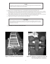
base module subassemblies. See Figure 2 for the proper order of assembly.
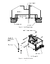
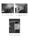
c. Join Base Sub-assemblies together. Use (4) 3/8”-16 x 3/4” screws, nuts and washers to attach subassemblies. (See
Figure 4)
d. Assemble the base in the location where the boiler is to be installed. Refer to Sections III and IV in this
manual for additional information on placement.
e. Once the base modules are assembled, install the base end panels. These base end panels must be installed
prior to assembling the sections.
f. The base must be level in both directions and supported under all feet. Shim and grout under base if
necessary.
g. Verify that the front and sides of the base are square.
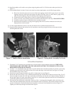
h. Place cardboard covering over the top of the burners to protect them during the assembly of the boiler
sections.
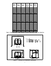
PACKAGE
JACKET SIDE PANEL CARTON
TANKLESS HEATER CARTON
POP SAFETY OR RELIEF VALVE
FITTINGS FOR MOUNTING POP SAFETY OR RELIEF VALVE
WARRANTY
PUSHNIPPLE GAUGE
RATING PLATE
SEALANT FOR SEALING HEAT EXCHANGER TO BASE
TANKLESS COIL OPENING COVER PLATES AND HARDWARE
A
SSORTED FITTINGS
INSTALLATION M ANUAL
USER'S M ANUAL
TANKLESS HEATER (IF USED)
LEFT AND RIGHT SIDE JACKET PANELS
LIMIT CONTROLS
GAUGE
LOW WATER CUT-OFF (CSD-1 BOILERS ONLY)
TANKLESS COIL OPENING COVER PLATES AND HARDWARE
A
SSORTED FITTINGS
LIMIT CONTROLS
GAUGE
LOW WATER CUT-OFFS
PUSHNIPPLE LUBRICANT
SECTION SEALING COMPOUND
BASE SIDE PANELS
BRACKETS AND HARDWARE FOR ATTACHING JACKET AND FLUE COLLECTOR TO SIDES OF BOILER
WATER TRIM CARTON
STEAM TRIM CARTON
BOILER CARTON
SUMMARY OF CONTENTS
BASE MODULE
BRACKETS AND HARDWARE FOR ATTACHING JACKET AND FLUE COLLECTOR
FRONT, TOP, REAR JACKET PANELS
FLUE COLLECTOR
PUSHNIPPLES
TIE ROD HARDWARE
BASE CARTON
INTERMEDIATE CARTON
SECTION JOINER CARTON
BASE SIDE PANEL CARTON