


40
38
DANGER
• CONFIRM RELIEF VALVE HAS THE CORRECT PRESSURE SETTING AND CAPACITY FOR THE
BOILER.
• PIPE THE PRESSURE RELIEF VALVE DISCHARGE TO A SAFE LOCATION.
• DO NOT INSTALL A VALVE IN THE RELIEF VALVE DISCHARGE LINE.
• DO NOT PLUG RELIEF VALVE DISCHARGE.
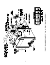
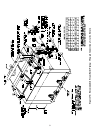
3) In addition to the boiler trim, the following system components are required:
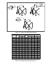
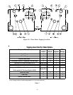
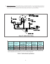
a. Circulator - The best circulator location is usually on the supply piping just downstream of the expansion
tank as shown in Figure 30.
b.
Expansion Tank - Consult the expansion tank manufacturer’s literature for proper sizing.
c. Fill Valve - Either a manual or automatic fill valve may be used. The fill connection should be located at the
expansion tank. On large systems with an automatic fill valve, it is recommended that a small water meter be
installed in the make-up water line to monitor the amount of water added to the system.
d.Air Elimination Device - At least one automatic air elimination device is required and should be located at the
expansion tank. Manual vents will usually be required in other parts of the system to facilitate the removal of air
during initial fill.
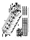
4) Certain systems will require additional considerations:
a. Low System Return Temperatures - The bypass piping shown in Figure 30 will minimize the amount of time that
the boiler operates with return temperatures below 120°F on these systems. A bypass is installed as shown to
divert some supply water directly into the return water. The bypass pipe should be the same size as the supply.
The two throttling valves shown are adjusted so that the return temperature rises above 120°F during the first few
minutes of operation. A three-way valve can be substituted for the two throttling valves shown.
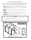
b.Systems containing oxygen - Many hydronic systems contain enough dissolved oxygen to cause severe corrosion
damage to a cast iron boiler such as the Series 32. Some examples include:
• Radiant systems that employ tubing without an oxygen barrier.
• Systems with routine additions of fresh water.
• Systems which are open to the atmosphere.
If the boiler is to be used in such a system, it must be separated from the oxygenated water being heated with a
heat exchanger. Consult the heat exchanger manufacturer for proper heat exchanger sizing as well as flow and
temperature requirements. All components on the oxygenated side of the heat exchanger, such as the pump and
expansion tank, must be designed for use in oxygenated water.
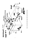
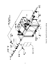
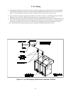
c. Piping with a Chiller - If the boiler is used in conjunction with a chiller, pipe the boiler and chiller in parallel.
Use isolation valves to prevent chilled water from entering the boiler. See Figure 31.
d.Air Handlers - Where the boiler is connected to air handlers through which refrigerated air passes, use flow
control valves in the boiler piping or other automatic means to prevent gravity circulation during the cooling
cycle.