


29
27
VIII Steam Boiler Piping & Trim Installation
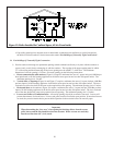
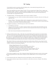
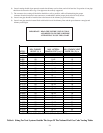
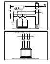
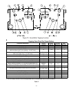
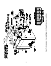
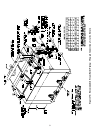
1) Figures 27 shows the recommended near boiler piping for most common types of gravity return steam systems. Use
Table 6 to determine the riser, header and equalizer piping sizes for the appropriate boiler model.
2) One of the primary purposes of the near boiler piping is to separate tiny water droplets from the steam exiting the
boiler so that “dry” steam is sent to the system. If the near boiler piping is not correct, wet steam will enter the
system and the following problems may occur:
• Short cycling on low water
• Boiler or system Flooding
• Hammering
• Failure to heat one or more radiators
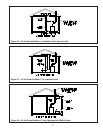
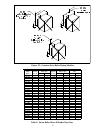
3) Avoid the three common piping mistakes shown in Figure 25. This applies even if the existing boiler has one of
the piping mistakes shown in Figure 25 and appears to be working. If two or more steam mains must be connected
to the boiler, connect a separate take-off for each main into the header between the riser(s) and equalizer. Also
note the following points:
a. A size reduction must be made to connect the header to the equalizer. This reduction must be made in the
equalizer line. Do not make this size reduction in the horizontal header.
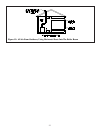
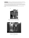
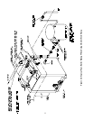
b.For installations with condensate or boiler feed pumps, follow the pump manufacturer’s piping instructions. Such
systems generally do not require Hartford loops. Figure 26 shows typical near-boiler piping when a boiler feed
pump is used.
c. Do not use a check valve in place of, or in addition to, a Hartford loop on a gravity return system.
d. Steam pipes shall have a clearance of at least 1/2” from all combustible construction.
e. Pipe the fill connection from a clean source of cold water. When the water supply is from a well, make sure that
a strainer is installed in the well system.
4) Boiler trim may be installed on either the left or right side of the boiler. Table 4B shows the uses of all steam boiler
tappings. The tapping letter designations referenced below are shown in Figure 22:
a. Pressure Gauge – Install in tapping “D”using the 1/2” nipple, tee and bushing provided. See Figure 23. DO
NOT TIGHTEN THE GAUGE BY ITS’ CASE.
b. Low Water Cut-off – Depending upon local codes, and how the boiler is ordered, one or more of the following
low water cut-offs may be used:
McDonnell & Miller #67 – Install in tappings “E”. If redundant low water cut-offs are used, the #67 must
be the back-up low water cut-off. The #67M (manual reset type) is standard on the CSD-1 control package
and should also be used when other codes require a back-up low water cut-off with manual reset.
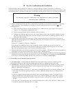
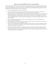
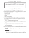
A. Heating System Piping (Steam Boilers)
CAUTION
• INSTALL BOILER SO THAT THE GAS IGNITION SYSTEM COMPONENTS ARE PROTECTED
FROM WATER (DRIPPING, SPRAYING, RAIN, ETC.) DURING APPLIANCE OPERATION
AND SERVICE (CIRCULATOR REPLACEMENT, ETC.).
• OPERATION OF THIS BOILER IN A SYSTEM HAVING SIGNIFICANT AMOUNTS OF
DISSOLVED OXYGEN CAN CAUSE SEVERE HEAT EXCHANGER CORROSION DAMAGE.