


31
29
Table 5
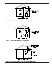
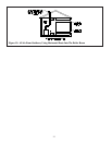
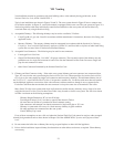
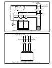
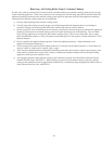
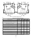
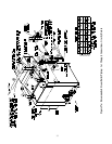
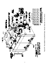
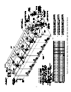
Figure 22: Steam Boiler Tapping Locations
Tapping Uses Chart For Steam Boilers
1
Component Description Tapping Tapping Standard CSD-1
Location Size (in) Equipment Package
Supply Piping A 3 N N
Return Piping B 3 N N
Safety Relief Valves
(With Inlet Opening Up To & Including 1-1/2" NPT Inlet)
Safety Relief Valves
(With Inlets Larger Than 1-1/2" NPT Inlet) Y Y
Pressure Gauge D 1/2 Y Y
Water Gauge Glass Fittings E 1/2 Y Y
M & M #67 Low Water Cut-Off E 1/2 Y N
M & M #67M Low Water Cut-Off with Manual Reset E 1/2 N Y
Hydrolevel CG450 Probe Low Water Cut-Off G 3/4 N Y
Steam Equalizer Installed On The End Not Equipped With Trim Between
(With Optional M & M #150 Float Low Water Cut-Off / Pump Controller) B & J
Honeywell PA404A Or L404A Pressure Limit D 1/2 Y Y
Boiler Drain Valve B 3 Y Y
Bottom Blowoff Piping B 3 N N
Cover Plate F - Y Y
Indirect Water Heater Connection H 1-1/2 N N
Indirect Water Heater Aquastat I 3/4 N N
1. Trim May Be Installed On Either End Section.
2. Use The Tapping Located On The End Not Equipped With Trim For The Safety Relief Valve & The Surface Blowoff .
Honeywell L404C Manual Reset Pressure Limit Control N Y
C
2
YY
NN
1-1/2
-
1/4" Tapping on
Top of #67 LWCO
-
3 & 1
Riser
(See Figure 27c)