


30
28
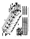
Hydrolevel CG450 – This is a probe type LWCO and is installed in tapping “G”. On the CSD-1 control
package, and other boilers with redundant low water cut-offs, the CG450 is the operating low water cut-off
and should be used to control a feeder (if used).
The CG450 supplied with the Series 32 uses a special probe which does not have a mounting flange.
Install this probe in tapping “G”. DO NOT INSTALL WITH TEFLON TAPE. With the jacket already
installed, installation of the probe is most easily done using a 1-1/16" deep throated socket. After the probe
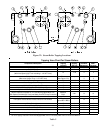
is installed, mount the case of the CG450 to the jacket using two #10 x ½ sheet metal screws through the
keyhole slots in the case (Figure 24). Connect the white probe wire to the wing nut on the probe. Note: A
direct ground connection between the case and the body of the probe is not required.
Other Low Water Cut-offs – Other float type low water cut-offs, such as the McDonnell & Miller #150
pump controller, are installed in an equalizing pipe connected between tappings “B” and “J”.
c. Gauge Glass – Install gauge glass in tappings “E” or in the #67 LWCO Tees (if used).
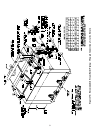
d. Pressure Limit Controls – All Series 32 steam boilers are supplied with a PA404A or L404A operating pressure
limit control. In addition, a manual reset L404C is supplied on boilers with the CSD-1 control package.
Install the PA404A using the straight pigtail siphon and bushing in the tee installed in Tapping “D”. See
Figure 23.
When an L404C is used, install it using the straight pigtail siphon in the 1/4” tapping on top of the #67 LWCO.
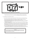
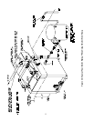
e. Safety Valve – Before installing the safety valve, examine the tag on the valve and confirm that it has a capacity
greater than or equal to the of the boiler’s gross output. Also confirm that its’ pressure setting is less than or
equal to that marked on the boiler sections (15 psi for steam). The location of the safety valve depends upon its’
size:
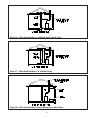
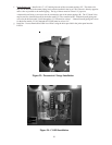
· Safety Valves of 1-1/2" and smaller are installed in one of the “C” tappings using the 1-1/2” nipple, tee and
bushing provided. See Figures 26 or 27. To do this, install a 1-1/2" nipple and 1-½” Tee in the “C” tapping
with the run of the Tee horizontal and the “bull” (side outlet) of the Tee pointing up. Install the Safety Valve in
the “bull” of the Tee and plug the remaining opening in the Tee. The use of a Tee to mount the relief valve
will permit Tapping “C” to also be used for skimming the boiler.
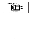
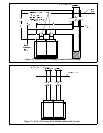
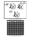
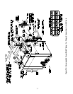
· Safety Valves greater than 1-1/2" must be installed in the steam riser with their spindle vertical (Figure 27c).
No valves are permitted between the boiler and the steam header.
Pipe the discharge of the safety valve to a location where hot water and steam will not create a hazard or cause
property damage if the valve opens. The discharge pipe must be the same size as the outlet connection on the
safety valve and must terminate in unthreaded pipe. The safety valve discharge piping must be in an area where it
is not likely to become plugged by debris or subjected to freezing.
DANGER
• CONFIRM SAFETY VALVE HAS THE CORRECT PRESSURE SETTING AND CAPACITY
FOR THE BOILER.
• PIPE SAFETY VALVE DISCHARGE TO A SAFE LOCATION.
• PIPING BETWEEN SAFETY VALVE CONNECTION AND BOILER MUST BE AT LEAST
AS LARGE AS SAFETY VALVE INLET CONNECTION.
• DO NOT INSTALL A VALVE IN THE SAFETY VALVE DISCHARGE LINE.
• DO NOT MOVE SAFETY VALVE FROM FACTORY LOCATION.
• DO NOT PLUG SAFETY VALVE DISCHARGE.
• DO NOT INSTALL A POP SAFETY VALVE WITH A SETTING GREATER THAN 15 PSI.