


16
14
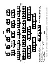
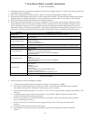
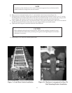
14) Install the tankless coil/s and/or cover plates using the gaskets and 3/8 x 7/8 bolts and washers provided (see
Figure 7).
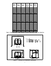
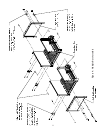
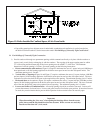
15) Test assembled block for leaks. Unless local codes have other requirements, use the following procedure:
a) Run a hose from the water service to one of the lower tappings. Install a ball or gate valve in one of the
tappings on the top of the block and connect the other end of this valve to a drain. Install a gauge in any
other convenient tapping. Plug all remaining unused tappings (See Figure 8).
b) Fill the boiler until a steady stream of water is observed going down the drain.
c) Slowly close the valve until the pressure in the boiler reads between 10 and 50 psi. DO NOT EXCEED.
d) Carefully examine all parts of the boiler block assembly for leaks.
e) Drain the boiler and remove all plugs from tappings that will be used for connections and trim (see
Piping Sections in this manual).
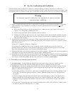
16) Use the supplied Resbond sealant to seal the joint between the assembled block and the base.
17) Inspect the joints between the sections for any areas that are not flue gas tight. Seal any areas found with the
remaining Resbond sealant.
Figure 8: Testing Boiler Assembly For Leaks
Figure 7: Tankless Heater Installation
D. Draft Hood Installation
1) The model 32-475 requires only one draft hood. All other boilers require multiple draft hoods. WHEN MUL-
TIPLE HOODS ARE USED THEY MUST BE ARRANGED SO THAT EACH HOOD IS OVER A COR-
RESPONDING SIZED BASE MODULE.
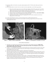
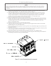
2) Use the 1" x ½” Cerablanket strips provided to seal the draft hoods to the block assembly. To do this, lay the strips
along the top of the block in the locations that will be under the edges of the draft hood (see Figure 9). Overlap
the Cerablanket strips at the corners.
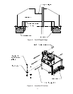
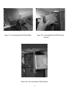
3) Install the rear panel support brackets using #10 x ½ sheet metal screws (Figure 3).
4) On the left end section, insert a 5/8 x 4 threaded stud through the available hole in the top rear tie rod lug. Use a 5/
8 nut and washer on each side of the lug to attach this stud, making sure that the stud is approximately centered on
the lug (See Figure 10). In the same manner, install 5/8 x 4" studs on the right end section and on all intermediate
sections that span the joint between base modules.
5) Place the left-most draft hood on the boiler. Insert two 5/16 x 3 carriage bolts through the holes in the lip on the
front of the hood with the head of the bolts on the underside of this lip. Thread a 5/16 washer and brass wing nuts
on each of these bolts. Slip the bolt heads into the pockets on the top of the intermediate sections (Figure 11).
Tighten just sufficiently enough to hold the hood in place.