


7
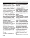
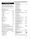
Dutchwest Direct Vent / Natural Vent Gas Heater
30001935
Max. Min.
Input Input
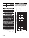
Model Fuel Gas Control BTU/h BTU/h
2465 Nat Millivolt 28,000 20,000
2466 Prop Millivolt 28,000 19,000
Gas Specifications
Weight: Fully assembled; 202 lbs.
Gas Inlet and Manifold Pressures
Natural LP (Propane)
Inlet Minimum 5.5” w.c. 11.0” w.c.
Inlet Maximum 14.0” w.c. 14.0” w.c.
Manifold Pressure 3.5” w.c. 10.0” w.c.
Dutchwest Direct Vent/Natural Vent
Certified to:
ANSI Z21.88-2005 / CSA 2.33-2005
Vented Gas Fireplace Heaters
The installation of your Dutchwest stove must
conform with local codes, or in the absence of lo-
cal codes, with the National Fuel Gas Code ANSI
Z223.1/NFPA 54 - latest edition, or CSA B149.1
Installation code. (EXCEPTION: Do not derate this
appliance for altitude up to 4,500 feet (1,370m).
Maintain the manifold pressure at 3.5” w.c. for
Natural Gas and 10.0” w.c. for LP Gas.
High Elevations
Input ratings are shown in BTU per hour and are
certified without deration for elevations up to
4,500 feet (1,370m) above sea level.
For elevations above 4,500 feet (1,370m) in USA,
installations must be in accordance with the
current ANSI Z223.1/NFPA 54 and/or local codes
having jurisdiction.
In Canada, please consult provincial and/or local
authorities having jurisdiction for installations at
elevations above 4,500 feet (1,370m).
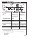
WARNING: Improper installation, adjustment,
alteration, service or maintenance can cause in-
jury or property damage. Refer to this manual for
correct installation and operational procedures.
For assistance or additional information consult
a qualified installer, service agency, or the gas
supplier.
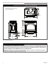
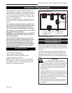
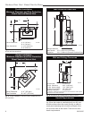
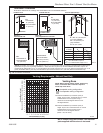
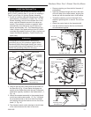
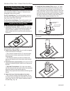
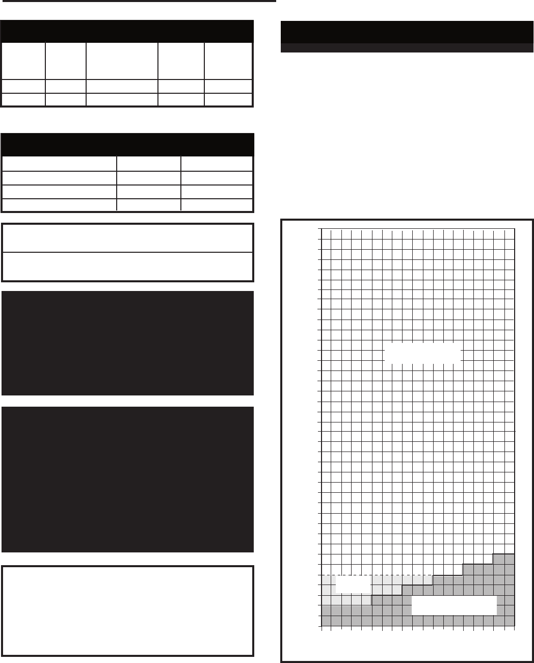
Horizontal Termination -
Direct Vent ONLY
The vent must rise vertically a minimum of 24” (610mm)
off the top of the unit, before the first elbow. The hori-
zontal run may extend up to 20’ (6m) and include a
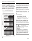
vertical rise of up to 40’ (12m). (Fig. 7) Horizontal
termination must also meet the criteria shown in Figures
9 through 11.
• Approved vent systems must terminate above and
including the heavy line in Figure 7.
• Two 45˚ elbows may be substituted for each single
90˚ elbow.
• With a rise between 2’ - 5’, one 90˚ or two 45˚ el-
bows may be used.
20
19
18
16
15
14
13
12
11
10
9
8
7
6
5
4
3
2
1
0
1 2 3 4 5 6 7 8 9
10 11 12 13 14 15 16 17 18 19 20
Vertical Run (in feet)
(Measured from the appliance flue collar to the top of the vent pipe.)
Horizontal Run (in feet)
21
22
23
24
25
26
27
28
29
30
31
32
33
34
35
36
37
38
39
40
ST134a
FDV28
Horizontal
vent run
12/3/99 djt
areas modified
1/11/00 djt
ST134a
Fig. 7 Horizontal vent termination window.
May use up to three
90° Elbows
One 90°
Elbow
Unacceptable Venting
Configuration