


26
Dutchwest Direct Vent / Natural Vent Gas Heater
30001935
Fuel Conversion Instructions
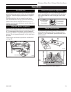
WARNING! This conversion kit shall be installed
by a qualified service agency in accordance with
the manufacturer’s instructions and all applicable
codes and requirements of the authority having
jurisdiction. If the information in these instruc-
tions is not followed exactly, a fire, explosion
or production of carbon monoxide may result
causing property damage, personal injury or loss
of life. The qualified service agency is respon-
sible for the proper installation of this kit. The
installation is not proper and complete until the
operation of the converted appliance is checked
as specified in the manufacturer’s instructions
supplied with the kit.
CAUTION: The gas supply shall be shut off prior
to disconnecting the electrical power, before pro-
ceeding with the conversion.
ST770
DW
attach gas line
5/15/03 djt
P
I
L
O
T
O
N
OFF
P
I
L
O
T
A
D
J
L
O
H
I
Gas Supply Inlet
Main Gas
Line
ST770
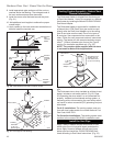
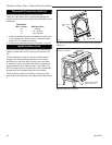
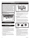
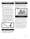
Fig. 48 Attach the gas line to the left side of the valve.
Conversion Precautions
Before proceeding, turn control knob on valve to OFF
and turn gas supply OFF. Turn OFF any electricity that
may be going to the appliance.
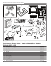
Conversion Procedure
1. Remove stove front. Lift stove front up and then
swing bottom out and away to disengage from the
stove body. (Fig. 58, Page 29)
2. Swing open the swiveling latches at the top left and
right corners of the glass frame. (Fig. 59, Page 29)
3. Pull the top edge of the glass and frame assembly
away from the firebox face. Place the assembly out
of the way on a flat, padded surface such as a coun
-
ter protected by a towel.
4. Remove the logset from the firebox.
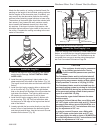
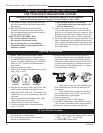
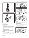
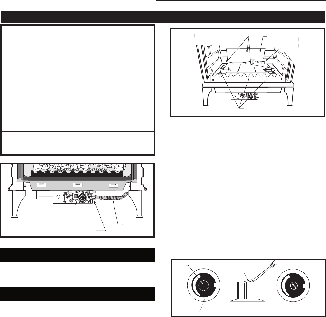
5. Remove the rear log bracket by unfastening the
screw. (Fig. 49)
6. Remove the right and left log bracket assembly by
unfastening the two screws which hold the burner in
place. (Fig. 49)
7. Hold the burner at the right hand side and lift to clear
the right burner leg. Then pull to the right to clear the
injectors on the left hand side.
8. Remove injector orifices from left burner leg using
1/2” wrench. (Fig. 55)
9. Install conversion orifices. (Refer to Table 2)
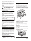
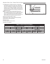
Honeywell Valve
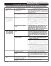
1. Remove cap from Hi-Lo knob. This can be accom
-
plished by lifting the plastic cap off the screw. (Fig.
50)
2. Remove the screw from center of Hi-Lo knob with
small screwdriver turning counterclockwise. (Fig. 50)
3. Insert blue painted screw when converting to natural
gas and red painted screw when converting to LP.
4. Tighten screw (do not over tighten), replace cap.
ST350
Jefferson
air shutter adj
3/20/00 djt
Remove Screws
Rear Log Bracket
Pilot
Left & Right Log
Bracket Assembly
ST768
Fig. 49 Remove rear log bracket and left and right log
bracket assembly.
CO100
Gas conversion
HI-LO knob
3/15/99 djt
L
O
H
I
L
O
H
I
Cap
Hi/Lo
Knob
Lift
Open
Center Screw
CO100
Fig. 50 Remove center screw from Hi/Lo knob.
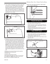
SIT 820 Valve
1. Using TORX T20 bit, remove and discard the three
(3) pressure regulator mounting screws (A), pressure
regulator tower (B) and the spring and diaphragm
assembly (C). (Fig. 51)
2. Insure the rubber gasket (D) is properly positioned
and install the new HI/LO pressure regulator assem-
bly to the valve using the new screws (E) supplied
with the kit. Tighten the screws securely. (Ref. torque
= 25 in/lb) (Fig. 52)
3. Install the enclosed conversion label (F) to the valve
body where it can easily be seen. (Fig. 52)