


21
Dutchwest Direct Vent / Natural Vent Gas Heater
30001935
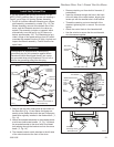
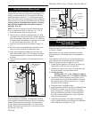
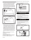
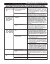
8. The air shutter is located on the bottom of the burner
to the left. (Fig. 37) Unfasten the two nuts holding
the shutter in place. The shutter may be adjusted
between the factory adjusted 1/2” to fully open.
Reassemble the shutter to allow the rear injector air
inlet to close from the minimum 1/2” opening to fully
open. (Fig. 39) You may have to try more than once
to find the correct air shutter opening for best results
depending on your altitude.
ST352
jeff
erson
air shutter
ne
w position
3/20/00 djt
Air Shutter
(Original Position)
Burner
See Table 1
ST352
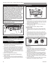
Fig. 38 Air shutter in original from-the-factory position.
Should color need further adjustment, repeat steps 1
- 12 for air shutter adjustment.
ST351
jef
ferson
air shutter
original position
3/20/00 djt
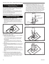
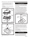
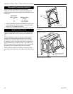
Front Injector
Air Inlet
Air Shutter
(May be adjusted up to fully open)
Burner
ST351
Rear Injector Air Inlet
Fig. 39 Air shutter adjusted.
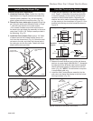
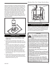
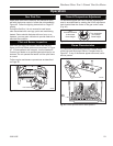
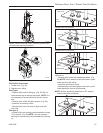
9. Refasten the two nuts and assemble the burner into
the unit by sliding the burner in at an angle with the
left side lower than the right side. Slide the left side
onto the injectors. Lower the right hand side down
into place. Make sure the burner is as far left as pos-
sible and the injector shoulders are inside the burner.
NOTE: It is very critical to keep the left burner leg,
which holds the injectors, at a 90° angle to the base.
(Fig. 40) This keeps the orifices aligned with tubes
on the inside of the burner. Failure to do so could
affect the flame appearance and performance of the
unit.
10.Refasten the right and left log bracket assembly.
11.Refasten the rear log bracket.
12.Replace logs.
13.Replace glass and stove front.
Follow lighting instructions on Page 25. Check flame
color appearance. NOTE: Allow stove to burn for at
least 1/2 hour to establish full flame color.
ST353
air shutter adjust
burner replace
3/20/00 djt
90°
Left Burner Leg
Injector Shoulder
ST353
Fig. 40 Be sure to maintain 90° angle at left burner leg.
Complete the Assembly
• Open the swiveling latches (cams) on the top left
and right corners of the glass frame.
• Position the glass and frame against the firebox by
placing the bottom edge on the brackets on the bot-
tom face of the firebox.
• Swing the assembly against the firebox, and close
the latches firmly against the pins protruding from
the firebox top.
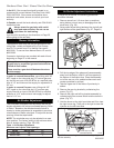
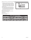
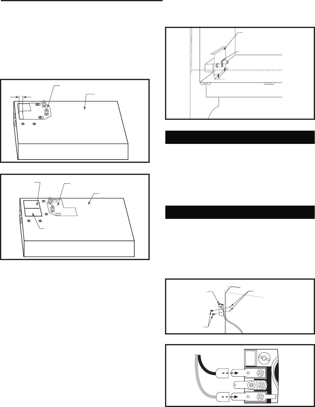
Install ON/OFF Switch
The switch assembly parts are found in the parts bag.
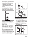
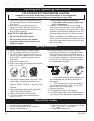
1. Attach switch assembly to left rear side of stove
shroud (when facing shroud) using two screws and
existing holes in shroud. (Fig. 41)
2. Run wires down back of stove, under bottom of rear
shroud to valve.
3. Attach wires to valve terminals. (Fig. 42)
ST315
attach switch assy
1/31/00 djt
Existing Holes
Switch Assembly
Screws
ST315
Fig. 41 Attach switch assembly to rear shroud.
PILOT
ADJ
TP
TH
TPTH
ST228
attach switch
wires to valve
12/99
ST228
Fig. 42 Attach switch wires to valve.