


22
Dutchwest Direct Vent / Natural Vent Gas Heater
30001935
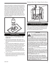
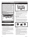
Thermostat Connection (optional)
Use only a thermostat rated for 500 millivolts.
Check the table below for the appropriate gauge ther-
mostat wire to use for the length of lead required in your
installation.
Thermostat
Wire / Gauge Maximum Run
18 20 feet
16 20 - 40 feet
14 up to 60 feet
1. Install the wall thermostat in the desired location and
run the wires to the stove location. Terminate these
leads with 1/4” female connectors.
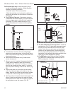
2. Connect the thermostat wires to the valve. (Fig. 42)
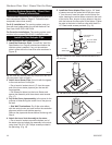
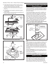
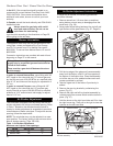
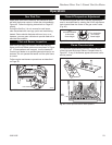
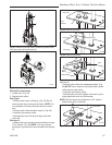
Install the Stove Front
Insert the handle stub into the hole in the front casting.
Fasten in place witht he 3/8” locking nut provided. (Fig.
43)
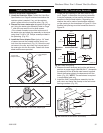
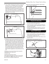
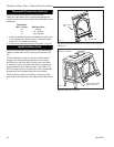
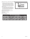
The front attaches to the stove by four steel tabs that
engage with corresponding cast ribs onto the sides
and bottom of the stove body. Position the front about
3” down from stove top and lift the plate to engage the
upper tabs behind the adjacent ribs on the sides. (Fig.
44) Then lower the front into position, so the lower tabs
engage with the corresponding ribs at the bottom.
When properly installed, the bottom of the stove front
cannot be pulled away from the sides without also lifting
it.
ST773
handle assy
6/6/03
3/8” Locking
Nut
Handle Stub
ST773
Fig. 43 Insert handle stub into hole in front. Secure with 3/8”
locking nut.
D
UTCH
W
EST
D
UTCH
W
EST
Est. 1974
ST771
DW
stove front
5/30/03 djt
Engage steel tabs behind
the cast iron bosses
Bottom tabs engage
notch in the leg
ST771
Fig. 44 Install the front plate.