


14
Dutchwest Direct Vent / Natural Vent Gas Heater
30001935
Venting System Assembly - Direct Vent
General Information
The Dutchwest is approved for installation only with the
vent components listed on Page 12. Follow the vent
component instructions exactly.
For U.S. installations: The venting system must con-
form with local codes and/or the current National Fuel
Gas Code, ANSI Z223.1/NFPA 54.
For Canadian installations: The venting system must
conform to the current CSA B149.1 installation code.
Install the Vent Adapter Pipe
(CFM Corporation Vent Components)
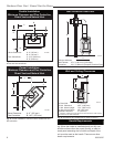
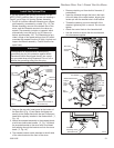
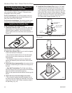
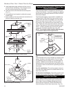
1. Install the Restrictor Plate. Consult the ‘Vent Run
Specifications’ on Page 8 to determine whether the
restrictor plate is needed. If so, put the restrictor
plate in place within the inner flue collar as shown in
Figure 16.
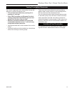
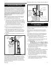
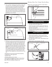
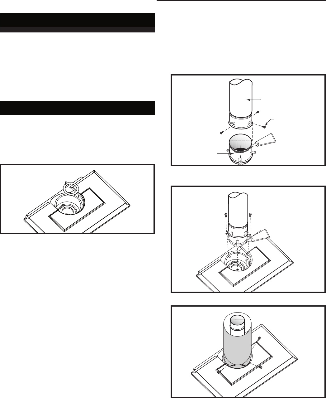
5. Install the Outer Adapter Pipe. Apply a 1/4” bead
of cement around the inside wall of the pipe, about
1” from the end. Insert the pipe over the stove flue
collar, keeping the vertical seam oriented to the back
of the stove. Also, be sure to align holes on the pipe
with the holes on the flue collar of the firebox. Fasten
the pipe to the holes in the flue collar with the #12 x
1/2” sheet metal screws provided. (Fig. 19)
ST759
Dutchwest
restictor plate
5/15/03
ST759
Fig. 16 Install the restrictor plate only if required for the vent-
ing configuration. Refer to Page 8.
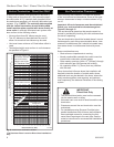
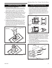
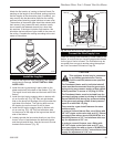
2. Attach Inner Starter Pipe, (found in with the logset),
to the next section of inner pipe.
• Run a bead of sealant about 1/2” from the upper
end of the Inner starter pipe and join the two sec-
tions together.
• Drill three pilot holes into the Inner Starter and
secure the assembly with three sheet metal screws.
(Fig. 17)
3. Dry fit the Outer pipe assembly to the stove for the
purpose of determining the center line of the pipe on
the wall.
• Side Wall Terminations: Dry fit the outer elbow
with the vertical outer vent and confirm the centerline
alignment with the wall thimble opening.
Remove the pipes and elbows before continuing with
Step 4.
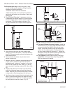
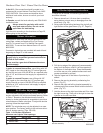
4. Attach the Inner Vent Assembly to the stove.
• Run a bead of sealant around the bottom end of
the starter pipe and attach the assembly to the stove
using three 1/4-20 x 3/8” Phillips screws provided in
the parts bag. (Fig. 18)
ST211
attach inner pipe
to next section
12/4/99 djt
CEMENT
First Section of
Vent Pipe
#8 x 1/2” Sheet
Metal Screws
4” Inner
Starter Pipe
ST211
Fig. 17 Connect the inner starter with the next section of in-
ner vent pipe.
ST760
attach inner assy
5/15/0 3 djt
CEMENT
ST760
Fig. 18 Attach inner assembly to flue collar.
ST761
attach inner assy
5/15/03 djt
ST761
Fig. 19 Fasten outer pipe with #12 x 1/2” sheet metal screw.