


25
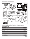
Dutchwest Direct Vent / Natural Vent Gas Heater
30001935
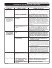
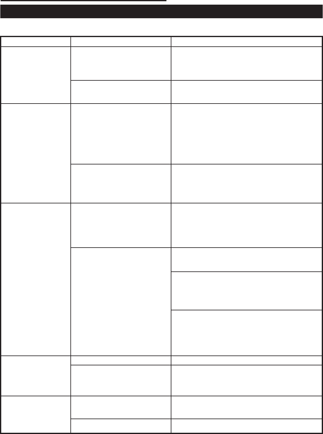
Troubleshooting / Honeywell #8420 Gas Control System
NOTE: Before troubleshooting the gas control system, be sure the external gas shutoff is in the “ON” position.
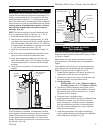
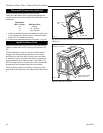
WARNING: REMOVE THE GLASS PANEL BEFORE PERFORMING ANY GAS CONTROL SERVICE WORK.
SYMPTOM POSSIBLE CAUSES CORRECTIVE ACTION
1. Spark ignitor will not
light
2. Pilot will not stay lit
after carefully fol-
lowing the lighting
instructions
3. Pilot lights, no gas to
burner, valve knob
ON, remote switch
(rocker switch) ON
4. Frequent pilot out
-
age
A. Defective or misaligned elec
-
trode at the pilot
B. Defective ignitor (push button)
A. Defective pilot generator (ther
-
mocouple)
B. Defective automatic valve op-
erator
A. Remote switch or wires defec
-
tive
B. Thermopile may not generate
sufficient voltage
C. Plugged burner orifice
D. Defective automatic valve op-
erator
A. Pilot flame may be too low or
high, (blowing or lifting), caus-
ing the pilot to drop out
B. Possible blockage of the vent
terminal
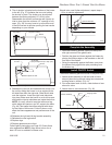
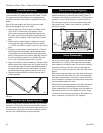
Using a match, light pilot. If pilot lights, turn off pilot
and push the ignitor button again. If pilot will not light,
check gap at electrode and pilot - it should be 1/8” to
have a strong spark.
Push piezo ignitor button. Check for spark at elec-
trode and pilot. If there is no spark at the pilot, and
electrode wire is properly connected, replace ignitor.
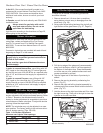
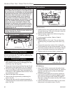
Check pilot flame. It must impinge on the thermo-
couple or thermopile. NOTE: This pilot burner as-
sembly uses both a thermocouple and a thermopile.
The thermocouple operates the pilot flame. Tighten
the thermocouple. The thermopile operates the main
valve (ON and OFF). Clean and/or adjust pilot for
maximum flame impingement on thermocouple and
thermopile.
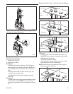
Turn valve knob to ‘Pilot’. Maintain flow to pilot; mil-
livolt meter should read greater than 10mV. If the
reading is okay and the pilot does not stay on, re-
place the gas valve. NOTE: An interrupter block (not
supplied) must be used to conduct this test.
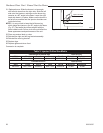
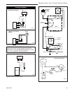
Check rocker switch and wires for proper connection.
Use jumper wires across terminals at rocker switch.
If burner lights, replace rocker switch. If okay, use
jumper wires across rocker switch wires at the valve;
if burner lights, wires are faulty or connections are
bad.
1. Be sure wire connections from thermopile at gas
valve terminals are tight and thermopile is fully
inserted into pilot bracket.
2. One of the rocker switch wires may be grounded.
Remove rocker switch wires from valve terminals.
If burner now stays lit, trace rocker switch wiring
from ground. It may be grounded to the appliance
or the gas supply line.
3.
Check the thermopile with a millivolt meter. Take
reading at thermopile (“TP” and “TP/TH”) terminals
of gas valve. Should read 325 millivolts minimum
while holding valve knob depressed in PILOT po-
sition and with rocker switch OFF. Replace faulty
thermopile if reading is below specified minimum.
Check burner orifices for debris, and remove.
Turn knob to ON, place rocker switch to ON, millivolt
meter should read greater than 10 mV. If the read-
ing is okay and the burner does not light, replace the
valve.
Clean and/or adjust pilot flame for maximum flame
impingement on thermocouple and thermopile.
Check the vent terminal for blockage.