


19
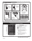
Dutchwest Direct Vent / Natural Vent Gas Heater
30001935
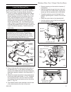
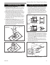
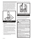
Attach the first section of venting to the draft hood. De-
pending on the length of the individual venting sections
and the lengths of the decorative pipe (if installed), you
may need to slip the decorative pipe over the venting
sections before attaching upper sections to lower ones.
The sections of decorative pipe should be oriented with
their seams (if any) toward the wall; sections usually
do not need to be fastened at each joint, other than
slip sections. If the layout includes a slip section, this
should be the last section of pipe visible in the room, at
the ceiling. Complete the venting according to the vent
maker’s instructions.
ST767
DW
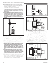
attach draft hood
5/15/03 djt
CEMENT
ST767
Fig. 33 Install draft hood adapter.
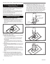
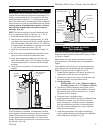
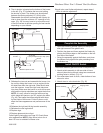
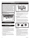
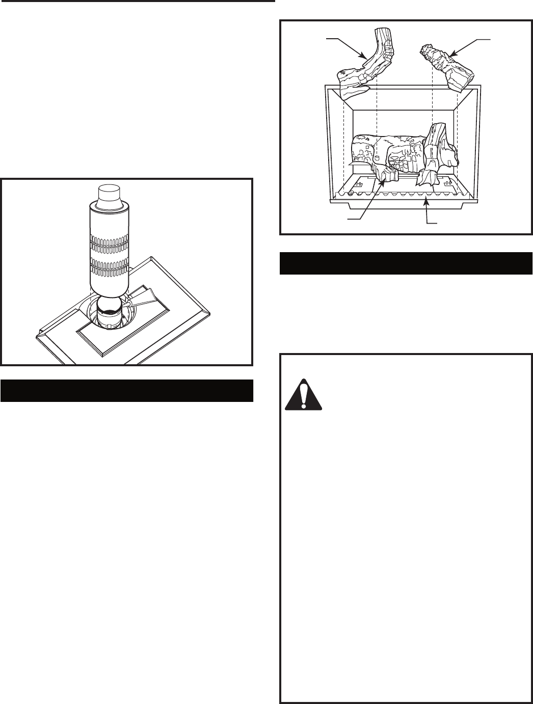
Install the Log Set
1. Remove the logs from their packaging, and inspect
each piece for damage. DO NOT INSTALL DAM-
AGED LOGS.
2. Install the rear log centering it side to side on the
sheet metal shelf at the back of the firebox. (Fig. 34)
The log will touch both sides and the back wall of the
firebox.
3. Install the right log by engaging hole on bottom with
pin on the rear log. (Fig. 34) Then set right bottom
side on the burner so the edge of the log touches the
right side of the firebox. The right log does not use
the locator pins on the burner to stay in place.
4. Install the left log by engaging hole on bottom with
pin on rear log. (Fig. 34) Then set left bottom side
on the burner so the edge of the log touches the left
side of the firebox.
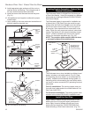
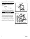
5. Loosely sprinkle the lava rocks directly on top of the
burner in front of and between the decorative grate
and the right and left logs. Use the lava rock to cover
brackets on the burner. (Fig. 35)
LG141
Stardance
Install logs 1
12/1
1/00 djt
Left Log
Right Log
Rear Log
Decorative Grate
LG141
Fig. 34 Install the back, left and right logs.
Connect the Gas Supply Line
Check the Rating Plate attached by a steel cable to the
firebox, to confirm that you have the appropriate firebox
for the type of fuel to be used. The Dutchwest may be
converted from one gas to another using the appropri-
ate Fuel Conversion Kit listed on Page 34.
CAUTION
This appliance should only be connected
by a qualified gas technician. Test to
confirm manifold pressures as specified
below.
The Dutchwest Heater and its individual shutoff
valve must be disconnected from the gas supply
piping during any pressure testing of that system
at test pressures in excess of 1/2 psig (3.5 kPa).
The Dutchwest Heater must be isolated from the
gas supply piping system by closing its individual
manual shutoff valve during any pressure testing
of the gas supply piping system at test pressure
equal to or less than 1/2 psig.
There must be a gas shutoff between the stove
and the supply.
In order to connect Natural Gas, use a fitting with
3/8” NPT nipple on the valve side and 1/2” natural
gas supply line with an input of 28,000 BTUs at a
manifold pressure of 3.5” and minimum inlet sup-
ply for adjustment of 5.5” w.c.
In order to connect Propane, use a fitting with
3/8” NPT nipple on the valve side and 1/2” pro-
pane gas supply line with an input of 28,000 BTUs
at a manifold pressure of 10.0” and minimum inlet
supply for adjustment of 11.0” w.c.