


The alarm codes for the IGC control board are shown in
Table 22.
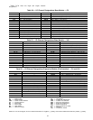
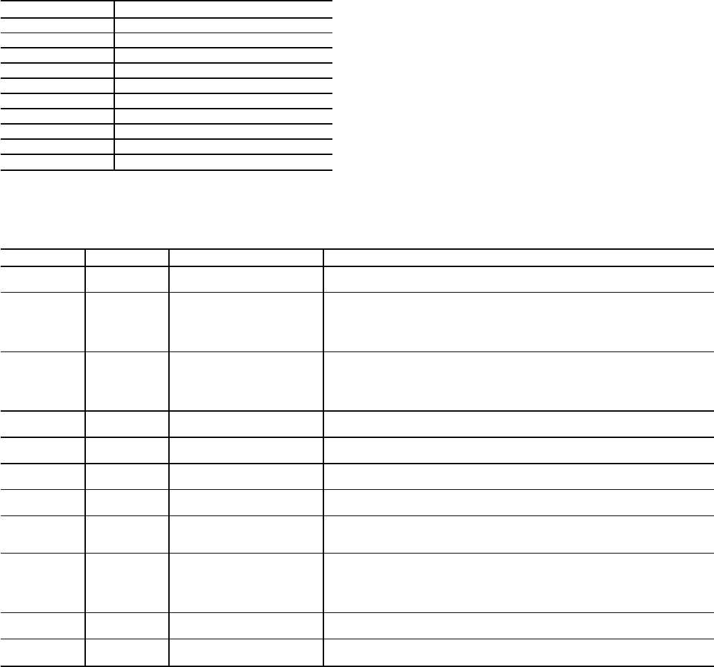
Table 22 — IGC Control Board LED Alarms
INDICATION ERROR MODE
ON Normal Operation
OFF Hardware Failure
1 FLASH Fan ON/OFF Delay Modified
2 FLASHES Limit Switch Fault
3 FLASHES Flame Sense Fault
4 FLASHES 4 Consecutive Limit Switch Faults
5 FLASHES Ignition Lockout Fault
6 FLASHES Induced Draft Motor Fault
7 FLASHES Rollout Switch Fault
8 FLASHES Internal Control Fault
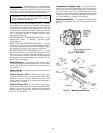
Diagnostic LEDs — There are 3 LEDs (red, yellow,
and green) on the lower right hand side of the control board.
The red light is used to check unit operation and alarms. A
constant pulse is normal unit operation. A series of quick
blinks indicates an alarm. Refer to Table 23 below for a de-
scription of alarms. The yellow LED blinks during transmis-
sion with the CCN (Carrier Comfort Network). The green
LED blinks during transmission with the expansion board.
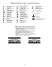
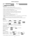
Table 23 — Control Board LED Alarms
LED Blinks Error Code Description Troubleshooting Comments
1 — Normal Operation
The expansion board and control board flash the red LED in one-second
intervals when the board is operating properly.
2 HF-13 Compressor 1 Safety
The high orlow pressure safety switch for compressor no.1 has opened for
3 seconds. The error will be cleared and compressor no. 1 will be allowed
to turn on in 15 minutes. If the safeties have been tripped 3 times in 90 min-
utes, compressor no. 1 will be locked out until the control board has been
manually reset.
3 HF-14 Compressor 2 Safety
The high orlow pressure safety switch for compressor no.2 has opened for
3 seconds. The error will be cleared and compressor no. 2 will be allowed
to turn on in 15 minutes. If the safeties have been tripped 3 times in 90 min-
utes, compressor no. 2 will be locked out until the control board has been
manually reset.
4 HF-15 Thermostat Failure
The thermostat iscalling for both heating and cooling at the same time. The
unit will operate on a first call basis and will automatically reset.
5 HF-05 SAT Thermistor Failure
The supply-air temperature (SAT) sensor has failed. First check for wiring
errors, then replace sensor.
6 HF-06 OAT Thermistor Failure
The outside air temperature (OAT) sensor has failed. First check for wiring
errors, then replace sensor.
7 HF-03 Space Temp. Sen. Failure
The space temperature sensor has failed. First check for wiring errors, then
replace sensor.
8 HF-12 RAT Thermistor Failure
The return-air temperature (RAT) sensor has failed. Ensure that the unit is
a VAV unit. If NOT a VAV unit set DIP switch position 1 to the closed position
and reset power. Then check for wiring errors. Finally, replace sensor.
9 SE-05
Loss of Communications
with Expansion Board
Communications between the expansion board and the control board have
been interrupted. Ensure that an expansion board is installed and wired us-
ing the wire harness supplied with the expansion module. If an expansion
board is not used ensure that DIP switch position 3 is in theclosed position,
and reset power.
10 HF-16 Control Board Failure
Generated when hardware has failed on control board. Replace the control
board.
11 HF-17 Expansion Board Failure
Generated when hardware has failed on the expansion board. Replace the
expansion board.
DIP — Dual In-Line Package
VAV — Variable Air Volume
60