


Features with Sensor Control of Unit (Network Applica-
tions) — The base control board provides, as standard, a con-
nection for use with a Carrier VVT system and can also be
integrated into a Carrier Comfort Network.
When the unit is accessed via a PC equipped with Com-
fortWorks™, Building Supervisor, or Service Tool software,
or accessory LID-2B, the following features can be
accessed:
• on-board timeclock can be programmed
• occupancy schedules can be programmed
• unit set points can be changed
• alarms can be monitored
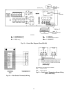
This access is available on the base control board via a
RJ-11 phone jack or a 3-wire connection to the communi-
cation bus. See Fig. 16. The timeclock has a 10-hour mini-
mum back-up time to provide for unit power off for servic-
ing unit or during unexpected power outages. For complete
Carrier Comfort System (CCS) or Carrier Comfort Network
(CCN) features and benefits, refer to the product literature.
VARIABLE AIR VOLUME (VAV) APPLICATIONS
Features with Stand-Alone Applications — The units, as
shipped, are operable as stand-alone units with the addition
of a timeclock to establish unit start and stop times.
Heating and cooling in both on and off modes is con-
trolled to default values by the base unit control. Set points
may be changed with appropriate input devices.
The control has an on-board occupancy schedule which
can be set using an input device and eliminates the need for
an external timeclock.
During both the on and off periods, cooling operation is
controlled to the supply air setting and heating is controlled
to the return air setting (or to the optional space temperature
sensor). During the on period, the supply fan runs continu-
ously. During the off period, the supply fan will be activated
if the return air sensor is outside of the set points and will
run log enough to accurately sample the space temperature.
The supply fan will then continue to run until any heating or
cooling load is satisfied, at which point it will turn off.
The use of a space sensor will allow for supply air reset
to conserve energy and maintain comfort. If equipped with
an override feature, the sensor will allow operation during
the off period for a fixed length of time.
Base unit control supports a Heat Interlock Relay (field
supplied) to fully open theVAV terminal devices during heat-
ing operation.
Standard features of a VAV unit with a remote start/stop
switch are:
• control board diagnostics
• control of an outdoor condenser fan based upon outdoor
air temperature
• control of modulating economizer to provide free cooling
when outdoor conditions are suitable, using supply-air tem-
perature as a set point
• support of remote occupied/unoccupied input to start or
stop the unit
• provide power exhaust output to an external power ex-
haust controller
• support supply-air temperature reset to offset supply air
set point
• support a field test for field check out
• support linkage to DAV systems
• cooling capacity control of up to 6 stages plus economizer
with compressors and unloaders to maintain supply air tem-
perature set point during occupied periods
• control of one stage of heat to maintain return-air tem-
perature at heating set point during occupied periods
• provide a variable frequency drive high voltage relay out-
put to enable VFD
• control of heat interlock relay
• compressor Time Guard override (power up, minimum off
and on times)
With the addition of a remote start/stop switch heating or
cooling is enabled during unoccupied periods as required to
maintain space temperature to within unoccupied set points.
Additional features may be provided with Electronic
Access to Unit Control Board. These features are:
• additional control board diagnostics
• electronic expansion board features (if installed)
• control of the economizer damper and indoor fan to obtain
unoccupied free cooling
• 365-day timeclock with backup (supports minute, hour, day,
month, and year)
• holiday table containing up to 18 holiday schedules
• occupancy control with 8 periods for unit operation
• support a set of display, maintenance, configuration, serv-
ice, and set point data tables for interface with Building
Supervisor, ComfortWorks, or Service Tool software soft-
ware or accessory LID-2B
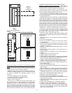
R
Y1
Y2
W1
W2
G
C
X
CONTROL
BOX
REMOTE
START/STOP
SWITCH
(FIELD-SUPPLIED)
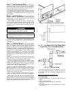
LEGEND
Field Supplied Wiring
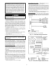
Fig. 14 — Field Control Remote Start/Stop
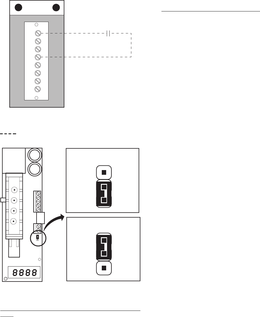
JUMPER CONNECTION
FOR VOLTAGE OUTPUT
JUMPER CONNECTION
FOR CURRENT OUTPUT
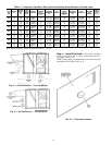
Fig. 15 — Indoor Air Quality Sensor Configuration
15