


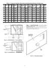
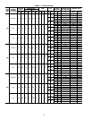
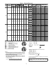
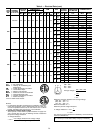
Table 4 — Electrical Data (cont)
UNIT
SIZE
48E
NOMINAL
VOLTAGE
(3 Ph 60 Hz)
VOLTAGE
RANGE
COMPRESSOR
OFM IFM
POWER
EXHAUST
COMBUSTION
FAN MOTOR
POWER SUPPLY
No. 1 No. 2
Min Max RLA LRA RLA LRA Qty Hp
FLA
(ea)
Hp FLA FLA LRA FLA MCA MOCP*
044
208/230 187 254 69.2 345 69.2 345 4 1 5.3
15
46.2/
42.0
— — 0.96 223.1/218.9 275/275
23.6 41.6 0.96 246.7/242.5 300/300
20
59.4/
54.0
— — 0.96 236.3/230.9 300/300
23.6 41.6 0.96 259.9/254.5 300/300
25
74.8/
68.0
— — 0.96 251.7/244.9 300/300
23.6 41.6 0.96 275.3/268.5 300/300
460 414 508 28.8 173 28.8 173 4 1 2.7
15 21.0
— — 0.50 96.6 125
12.6 23.6 0.50 109.2 125
20 27.0
— — 0.50 102.6 125
12.6 23.6 0.50 115.2 125
25 34.0
— — 0.50 109.6 125
12.6 23.6 0.50 122.2 150
575 518 632 26.7 120 26.7 120 4 1 2.4
15 17.0
— — 0.50 86.7 110
12.6 23.6 0.50 99.3 125
20 22.0
— — 0.50 91.7 110
12.6 23.6 0.50 104.3 125
25 27.0
— — 0.50 96.7 110
12.6 23.6 0.50 109.3 125
048
208/230 187 254 82.1 446 69.2 345 4 1 5.3
20
59.4/
54.0
— — 0.96 252.4/247.0 300/300
23.6 41.6 0.96 276.0/270.6 300/300
25
74.8/
68.0
— — 0.96 267.8/261.0 300/300
23.6 41.6 0.96 291.4/284.6 300/300
30
88.0/
80.0
— — 0.96 281.0/273.0 300/300
23.6 41.6 0.96 304.6/296.6 350/300
460 414 508 42.3 223 28.8 173 4 1 2.7
20 27.0
— — 0.50 119.5 150
12.6 23.6 0.50 132.1 150
25 34.0
— — 0.50 126.5 150
12.6 23.6 0.50 139.1 175
30 40.0
— — 0.50 132.5 150
12.6 23.6 0.50 145.1 175
575 518 632 34.6 164 26.7 120 4 1 2.4
20 22.0
— — 0.50 101.6 125
12.6 23.6 0.50 114.2 125
25 27.0
— — 0.50 106.6 125
12.6 23.6 0.50 119.2 150
30 32.0
— — 0.50 111.6 125
12.6 23.6 0.50 124.2 150
LEGEND
or
FLA — Full Load Amps
HACR — Heating, Air Conditioning and
Refrigeration
IFM — Indoor (Evaporator) Fan Motor
LRA — Locked Rotor Amps
MCA — Minimum Circuit Amps
MOCP — Maximum Overcurrent Protection
NEC — National Electrical Code
OFM — Outdoor (Condenser) Fan Motor
RLA — Rated Load Amps
*Fuse or HACR circuit breaker.
NOTES:
1. In compliance with NEC requirements for multimotor and combi-
nation load equipment (refer to NEC Articles 430 and 440), the
overcurrent protective device for the unit shall be fuse or HACR
breaker. Canadian units may be fuse or circuit breaker.
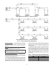
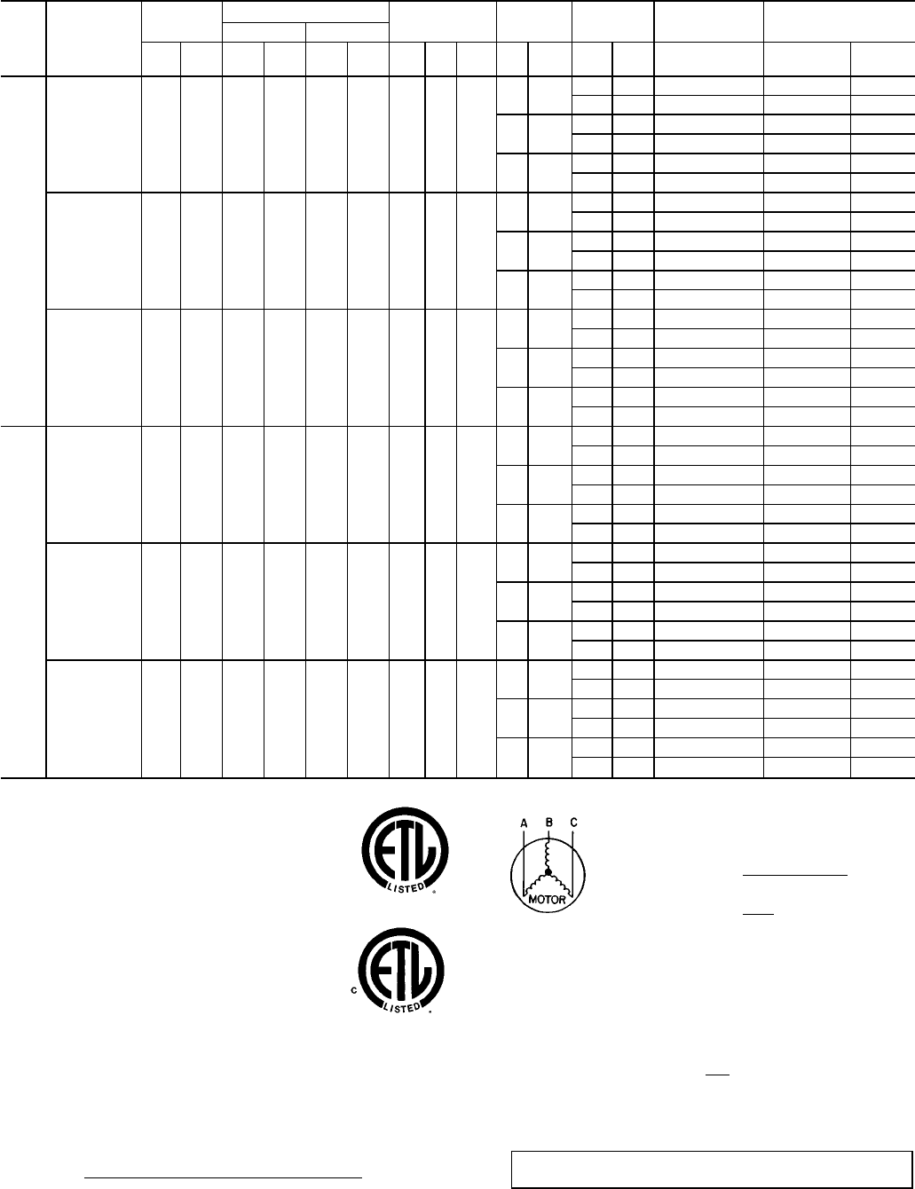
2. Unbalanced 3-Phase Supply Voltage
Never operate a motor where a phase imbalance in supply volt-
age is greater than 2%.
Use the following formula to determine
the percent voltage imbalance.
% Voltage Imbalance
max voltage deviation from average voltage
= 100 x
average voltage
EXAMPLE: Supply voltage is 460-3-60.
AB = 452 v
BC = 464 v
AC = 455 v
452 + 464 + 455
Average Voltage =
3
1371
=
3
= 457
Determine maximum deviation from average voltage.
(AB) 457 − 452=5v
(BC) 464 − 457=7v
(AC) 457 − 455=2v
Maximum deviation is 7 v.
Determine percent voltage imbalance.
7
% Voltage Imbalance = 100 x
457
= 1.53%
This amount of phase imbalance is satisfactory as it is below the
maximum allowable 2%.
IMPORTANT:If the supply voltagephase imbalance ismore than
2%, contact your local electric utility company immediately.
20