


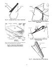
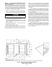
Step 10 — Position Power Exhaust/Barometric
Relief Damper Hood —
All electrical connections have
been made and adjusted at the factory. The power exhaust
blowers and barometric relief dampers are shipped as-
sembled and tilted back into the unit for shipping. Brackets
and extra screws are shipped in shrink wrap around the damp-
ers. If ordered, each unit will have 4 power exhaust blowers
and motors or 4 barometric relief dampers.
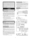
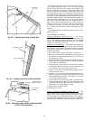
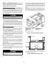
1. Remove 9 screws holding each damper assembly in place.
See Fig. 37. Each damper assembly is secured with 3 screws
on each side and 3 screws along the bottom. Save screws.
Be careful when tiltingblower assembly. Hoods and blow-
ers are heavy and can cause injury if dropped.
2. Pivot each damper assembly outward until edges of damper
assembly rest against inside wall of unit.
3. Secure each damper assembly to unit with 6 screws across
top (3 screws provided) and bottom (3 screws from
Step 1) of damper.
4. With screws saved from Step 1, install brackets on each
side of damper assembly.
5. Remove tape from damper blades.
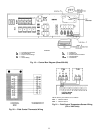
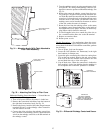
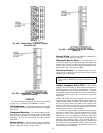
VAV DUCT PRESSURE TRANSDUCER — The VAV duct
pressure transducer (VAV inverter pressure transducer) is lo-
cated behind the filter access door on the lower inner panel.
See Fig. 38. A section of field-supplied
1
⁄
4
-in. plastic tubing
must be run from the high pressure tap on the differential
pressure switch and connected to a field-supplied tap in the
supply-air duct. The tap is usually located
2
⁄
3
of the way out
on the main supply duct. Remove plug button in panel to
route tubing.
The low pressure tap is factory-routed to the atmo-
sphere. For a positive-pressure building, route the high tap
to building air and low tap to atmosphere. For a negative-
pressure building, route the high tap to atmosphere and the
low tap to building air.
VAV BUILDING PRESSURE TRANSDUCER — The VAV
building pressure transducer (modulating power exhaust pres-
sure transducer) is located behind the filter access door on
the lower inner panel. See Fig. 38. A section of field-
supplied
1
⁄
4
-in. plastic tubing must be run from the high pres-
sure tap on the differential pressure switch to the conditioned
space. The pressure tube must be terminated in the condi-
tioned space where a constant pressure is required. This lo-
cation is usually in an entrance lobby so that the building
exterior doors will open and close properly. Remove plug
button in panel to route tubing.
The low pressure tap is factory-routed to the atmo-
sphere. For a positive-pressure building, route the high tap
to building air and low tap to atmosphere. For a negative-
pressure building, route the high tap to atmosphere and the
low tap to building air.
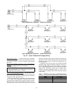
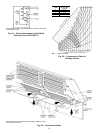
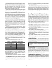
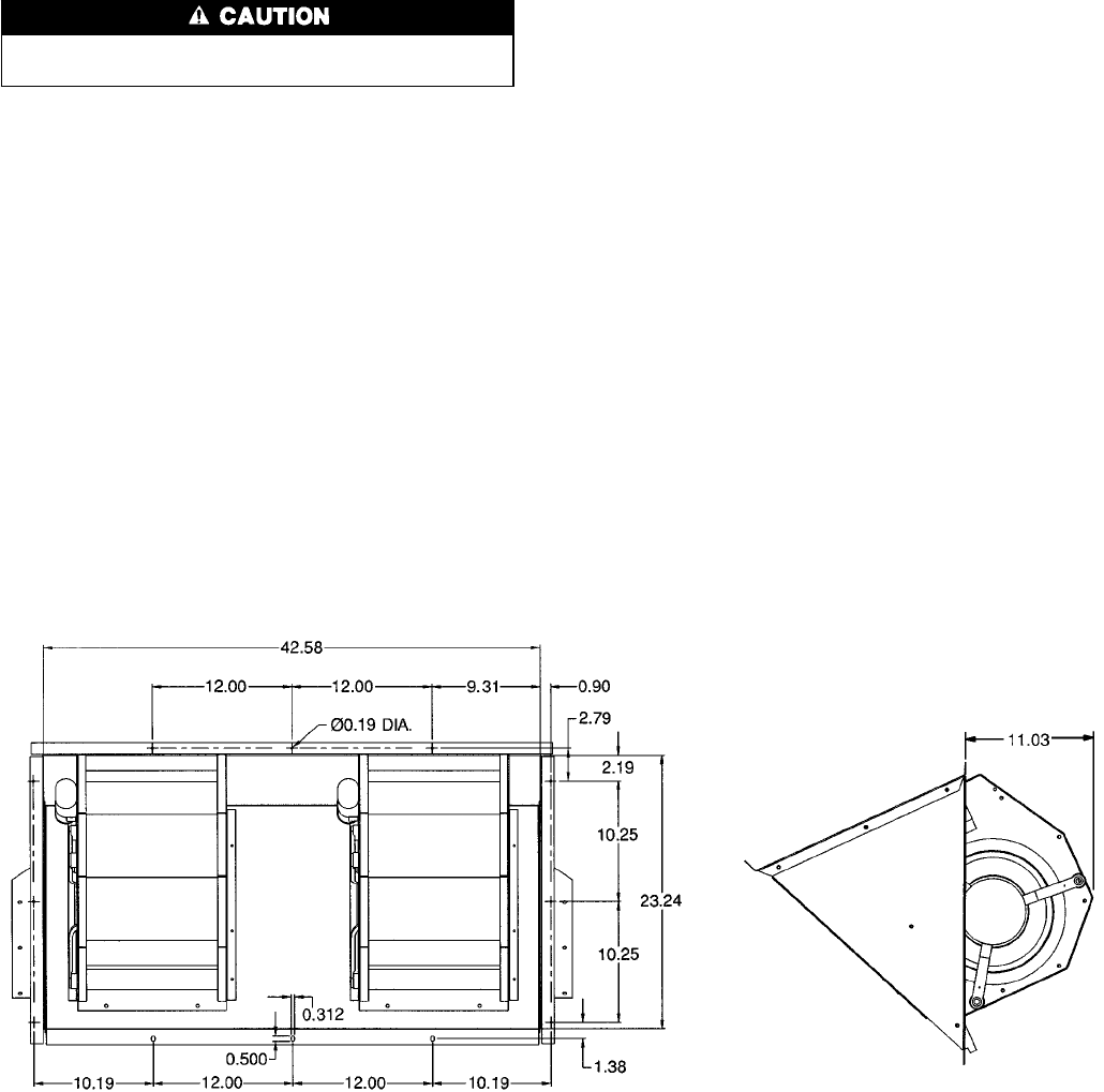
NOTES:
1. Unless otherwise specified, all dimensions are to outside of part.
2. Dimensions are in inches.
3. On 48EW,EY units, accessory barometric relief or power exhaust must be mounted in the field-supplied return ductwork.
Fig. 37 — Barometric Relief Damper and Power
Exhaust Mounting Details
29